2010 FORD F750 clutch
[x] Cancel search: clutchPage 131 of 274

Vehicles equipped with an Allison 3000 Series automatic
transmission
The PTO drive gear is engine-driven and provides direct engine power.
The PTO can be operated when the vehicle is either stationary or
moving.
The PTO gear is in constant mesh with the drive gear in the torque
converter housing. A friction clutch or constant drive is used to transmit
power to the PTO.
Vehicles equipped with a Caterpillar engine
The PTO will only operate if the transmission is in N (Neutral). This
feature can be overridden by a special service tool; see your dealer or
service representative for more information.
Vehicles equipped with a manual transmission
Transmission-mounted PTO units are available for local installation on
your vehicle. See yourBody Builder’s Layout Bookfor restrictions on
use and installation of PTO units.
To engage the PTO unit, stop the vehicle and place the transmission in N
(Neutral). Press the clutch and allow the gears to stop rotating, then
engage the PTO unit. The PTO can also be selected with the
transmission in gear as long as the clutch is pressed.
When operating the PTO with the vehicle stationary, first set the parking
brake (chock the wheels if the vehicle is on a hill or another uneven
surface).
REAR AXLE INFORMATION
Axle operating temperature normally will not exceed 100°F (38°C). If
the operating temperature exceeds 230°F (110°C), the rate of axle
lubrication oxidation will increase and shorten the life of the lubricant
and seals, requiring axle lubrication changes to become more frequent to
preserve the axle. Extreme Pressure (EP) lubricants should not be run
consistently above 230°F (110°C).
Gross axle weight
Your truck has gross axle weight, gross vehicle weight and gross
combination weight ratings. Do not exceed these ratings.
Driving
131
2010 F-650/750(f67)
Supplement(supplement), 1st Printing
USA(fus)
Page 134 of 274

Axle shifting
Manual transmissions:
•To downshift,select the next lower gear, release and press the
accelerator pedal rapidly, or while holding the accelerator pedal down,
release and engage the clutch rapidly.Note:The clutch method is
recommended when driving at slower speeds.
•To upshift,keep the accelerator pedal down, select the next higher
gear, release the accelerator and pause until the axle upshifts.Note:
De-clutch for smoother axle upshifts when driving at slower speeds.
Automatic transmissions:
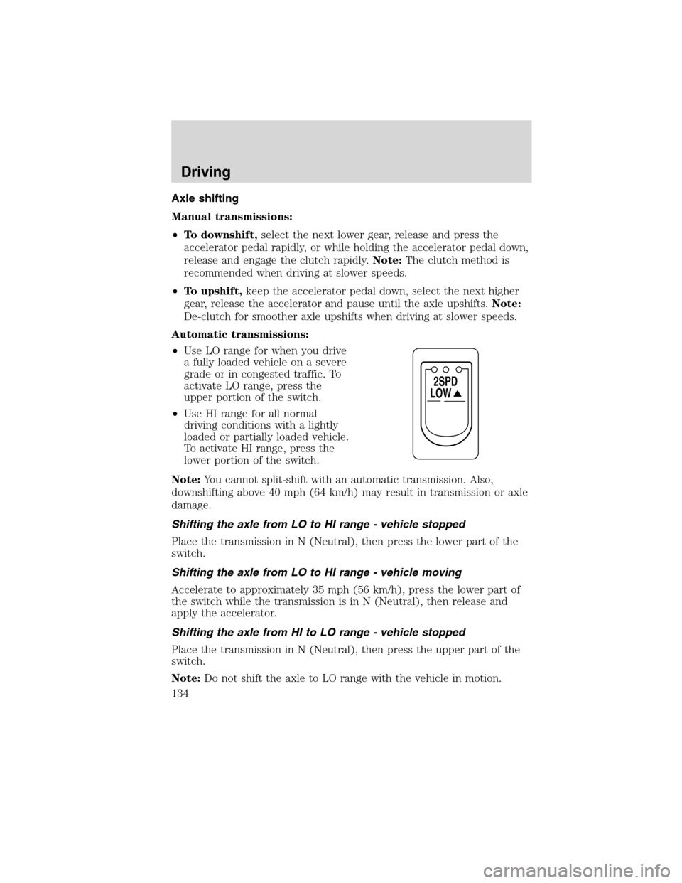
•Use LO range for when you drive
a fully loaded vehicle on a severe
grade or in congested traffic. To
activate LO range, press the
upper portion of the switch.
•Use HI range for all normal
driving conditions with a lightly
loaded or partially loaded vehicle.
To activate HI range, press the
lower portion of the switch.
Note:You cannot split-shift with an automatic transmission. Also,
downshifting above 40 mph (64 km/h) may result in transmission or axle
damage.
Shifting the axle from LO to HI range - vehicle stopped
Place the transmission in N (Neutral), then press the lower part of the
switch.
Shifting the axle from LO to HI range - vehicle moving
Accelerate to approximately 35 mph (56 km/h), press the lower part of
the switch while the transmission is in N (Neutral), then release and
apply the accelerator.
Shifting the axle from HI to LO range - vehicle stopped
Place the transmission in N (Neutral), then press the upper part of the
switch.
Note:Do not shift the axle to LO range with the vehicle in motion.
LOW
2SPD
Driving
134
2010 F-650/750(f67)
Supplement(supplement), 1st Printing
USA(fus)
Page 135 of 274

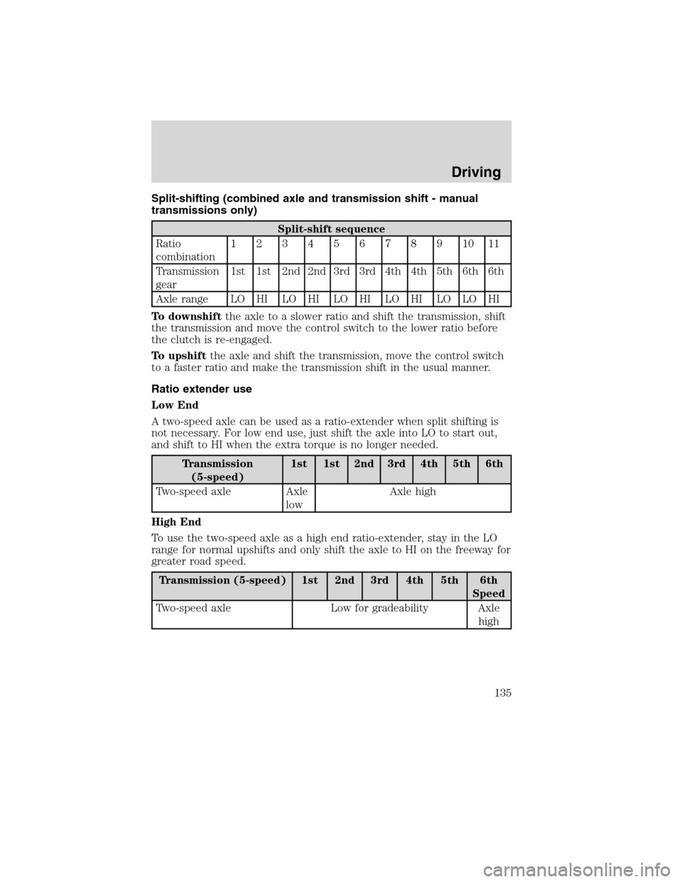
Split-shifting (combined axle and transmission shift - manual
transmissions only)
Split-shift sequence
Ratio
combination1234567891011
Transmission
gear1st 1st 2nd 2nd 3rd 3rd 4th 4th 5th 6th 6th
Axle range LO HI LO HI LO HI LO HI LO LO HI
To downshiftthe axle to a slower ratio and shift the transmission, shift
the transmission and move the control switch to the lower ratio before
the clutch is re-engaged.
To upshiftthe axle and shift the transmission, move the control switch
to a faster ratio and make the transmission shift in the usual manner.
Ratio extender use
Low End
A two-speed axle can be used as a ratio-extender when split shifting is
not necessary. For low end use, just shift the axle into LO to start out,
and shift to HI when the extra torque is no longer needed.
Transmission
(5-speed)1st 1st 2nd 3rd 4th 5th 6th
Two-speed axle Axle
lowAxle high
High End
To use the two-speed axle as a high end ratio-extender, stay in the LO
range for normal upshifts and only shift the axle to HI on the freeway for
greater road speed.
Transmission (5-speed) 1st 2nd 3rd 4th 5th 6th
Speed
Two-speed axle Low for gradeability Axle
high
Driving
135
2010 F-650/750(f67)
Supplement(supplement), 1st Printing
USA(fus)
Page 158 of 274

4. If tapered dowels are required, install them at each stud and into the
flange of the axle shaft. Use a punch or drift and hammer, if needed.
5. Install the fasteners and tighten to correct torque value. Refer to the
Service Manual.
Towing the vehicle with the rear wheels suspended
Note:To avoid damage to the cab roof or air deflector when towing the
vehicle backward (rear wheels suspended) the air deflector must be
removed.
Whenever possible, it is preferable to tow a disabled vehicle from the
rear by raising the rear of the chassis. When towing a vehicle with the
rear of the chassis suspended, the front wheels must be locked in the
straight-ahead position.
Vehicles equipped with a manual transmission must have at least 1.0 pint
(0.5L) of transmission fluid drained from the case. This will prevent the
transmission fluid from entering the clutch housing and fluid saturating
the clutch discs. Make sure that the transmission fluid is replaced before
the vehicle is returned to service.
Roadside Emergencies
158
2010 F-650/750(f67)
Supplement(supplement), 1st Printing
USA(fus)
Page 169 of 274

GENERAL SERVICING GUIDELINES AND PRECAUTIONS
As with any machine, care should be taken to avoid being injured when
performing maintenance, repairs or system checks. Improper or
incomplete service could result in the vehicle not working properly
which, in turn, may result in personal injury or damage to the vehicle or
equipment. It is the operator’s responsibility to see that the vehicle
receives proper care and maintenance. If you have any questions about
performing some service, have the service done by a qualified technician.
Servicing guidelines
When servicing your vehicle, always:
•turn off the ignition unless the particular procedure calls for the
engine to be running.
•set the parking brake or chock the wheels.
•use support stands, not a jack, whenever you must be under a raised
vehicle.
•do not smoke.
•wear safety glasses for eye protection.
•operate the engine in a well-ventilated area
•do not work on the brakes or the clutch unless the proper precautions
are taken to avoid inhaling friction material dust.
•do not wear loose-fitting clothing, hanging jewelry, watches or rings.
•avoid contact with hot metal parts. Allow the hot components to cool
before working with, or around them.
Quality service parts are available through your dealer. If dealer parts are
not used, the owner must make sure that the parts that are being used
are equivalent quality to dealer parts.
WARNING:The use of inferior parts can adversely affect the
quality and reliability of your vehicle which, in turn, can result in
property damage, personal injury or death.
Note:To avoid damage to the vehicle’s electrical components, disconnect
the positive (+) and negative (-) battery cables prior to electric welding.
Attach the welder ground cable as close as possible to the part being
welded. If it is necessary to weld close to an electrical component, it is
recommended that the electronic component be temporarily removed.
Follow the periodic lubrication procedures and regular inspection
intervals as outlined. Have your dealer or service center inspect your
Maintenance and Specifications
169
2010 F-650/750(f67)
Supplement(supplement), 1st Printing
USA(fus)
Page 184 of 274

Fan clutches
Your vehicle’s cooling system is equipped with a viscous fan clutch.
•The fan clutch helps control cooling, increase performance, improve
fuel economy and reduce noise.
•The fan clutch is controlled by bimetallic spring sensors. Do not
tamper with these sensors as this may change their calibration or keep
the fan clutch from operating at all.
WARNING:Stay clear of the fan/fan area while the engine is
running or possible personal injury may occur.
FUEL FILTER/WATER SEPARATOR
WARNING:Do not drain water separator while engine is
running. Fuel may ignite if separator is drained while engine is
running or vehicle is moving.
The fuel filter/water separator removes any contaminated particles
and/or water from the fuel before the fuel enters the engine.
Refer to your engine operator’s manual for information on draining and
replacing the fuel filter.
FUEL INFORMATION
Important safety precautions
WARNING:Do not overfill the fuel tank. The pressure in an
overfilled tank may cause leakage and lead to fuel spray and fire.
WARNING:The fuel system may be under pressure. If the fuel
cap is venting vapor or if you hear a hissing sound, wait until it
stops before completely removing the cap.
WARNING:Automotive fuels can cause serious injury or death
if misused or mishandled.
Maintenance and Specifications
184
2010 F-650/750(f67)
Supplement(supplement), 1st Printing
USA(fus)
Page 192 of 274

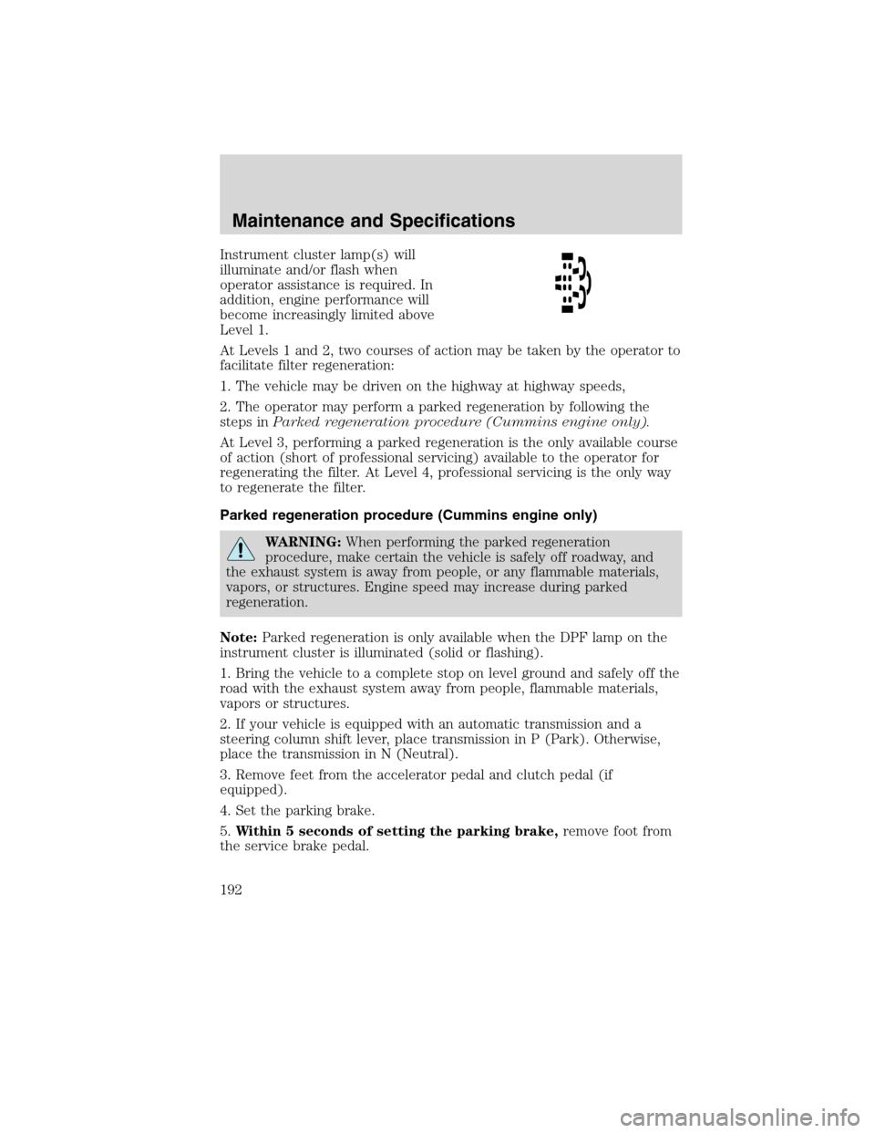
Instrument cluster lamp(s) will
illuminate and/or flash when
operator assistance is required. In
addition, engine performance will
become increasingly limited above
Level 1.
At Levels 1 and 2, two courses of action may be taken by the operator to
facilitate filter regeneration:
1. The vehicle may be driven on the highway at highway speeds,
2. The operator may perform a parked regeneration by following the
steps inParked regeneration procedure (Cummins engine only).
At Level 3, performing a parked regeneration is the only available course
of action (short of professional servicing) available to the operator for
regenerating the filter. At Level 4, professional servicing is the only way
to regenerate the filter.
Parked regeneration procedure (Cummins engine only)
WARNING:When performing the parked regeneration
procedure, make certain the vehicle is safely off roadway, and
the exhaust system is away from people, or any flammable materials,
vapors, or structures. Engine speed may increase during parked
regeneration.
Note:Parked regeneration is only available when the DPF lamp on the
instrument cluster is illuminated (solid or flashing).
1. Bring the vehicle to a complete stop on level ground and safely off the
road with the exhaust system away from people, flammable materials,
vapors or structures.
2. If your vehicle is equipped with an automatic transmission and a
steering column shift lever, place transmission in P (Park). Otherwise,
place the transmission in N (Neutral).
3. Remove feet from the accelerator pedal and clutch pedal (if
equipped).
4. Set the parking brake.
5.Within 5 seconds of setting the parking brake,remove foot from
the service brake pedal.
Maintenance and Specifications
192
2010 F-650/750(f67)
Supplement(supplement), 1st Printing
USA(fus)
Page 193 of 274

The engine speed may increase slightly. To allow parked regeneration to
continue uninterrupted:
1. The vehicle must remain parked
2. The transmission must remain in P (Park) or N (Neutral) (as
previously described in Step 2).
3. The accelerator pedal, service brake pedal, and clutch pedal (if
equipped) must not be pressed
4. The parking brake must remain set
On average (depending on filter level and other factors), the process will
take 20–30 minutes to complete. The DPF lamp will turn off when the
process is complete. Repeat Steps 1–5, if parked regeneration is interrupted.
To discontinue parked regeneration (Cummins engine only)
Press any of the floor pedals to discontinue parked regeneration.
Diesel particulate filter maintenance and service
The DPF is designed to retain a relatively large amount of residual ash
and provide many miles and hours of maintenance-free operation. At
some point, generally beyond 150,000 miles (240,000 km) or 5,000 hours
of operation (whichever comes first), the DPF will require professional
cleaning to remove the accumulated ash
The exact number of miles or hours of operation will vary greatly
depending upon vehicle/engine loading and operating conditions, ash
content of the engine oil, and quality of the diesel fuel used in your
truck. Adhering to your engine manufacturer’s recommended oil and fuel
specifications will maximize the miles and hours of operation before a
DPF professional cleaning is required. Refer to your engine
manufacturer’s owner’s manual for more details regarding recommended
maintenance and service of your DPF.
Exhaust outlet assembly
WARNING:The normal operating temperature of the exhaust
system is very high. Never work around or attempt to repair any
part of the exhaust system until it has cooled. Failure to follow these
instructions may result in serious personal injury.
The exhaust outlet assembly on your vehicle is a uniquely functioning
device that accompanies the DPF assembly. It is designed to help control
the temperature of the exhaust during the DPF regeneration process.Do
Maintenance and Specifications
193
2010 F-650/750(f67)
Supplement(supplement), 1st Printing
USA(fus)