2010 FORD F650 tires
[x] Cancel search: tiresPage 17 of 274

Front brakes
Hoses:Check for cracked, worn or frayed hoses. Make
sure all couplings are secured.
Chambers:Make sure brake chambers are not cracked or
dented and that they are securely mounted.
Slack adjuster:Check for broken, loose or missing parts. The
angle between the push rod and adjuster arm
should be approximately 90° when the brakes
are applied. When pulled by hand, the push
rod should not move more than approximately
one inch (2.5 cm).
Drum:Make sure there are no cracks, dents or holes
and no loose or missing bolts. Make sure brake
linings are not worn, dangerously thin or
contaminated by lubricant.
Front wheels
Rims:Check for damaged or bent rims. Rims should
not have welding repairs and no rust trails that
indicate it is loose on the wheel.
Lug nuts:Make sure all lug nuts are present and not
loose (look for rust trails around the lug nuts).
There should be no cracks radiating from the
lug bolt holes or distortion of the bolt holes.
Hub oil seal:Check wheel hub oil seal for leaks, and if sight
glass if present, check to see that the oil level
is adequate.
Oil-lubricated front
wheel bearing:If the hubcap has a transparent window, check
for proper lubrication level. If the hubcap does
not have a transparent window, remove the
rubber fill-plug and check for proper level.
WARNING:If a wheel must be changed, obtain expert tire
service help. Mounting and un-mounting of tires should only be
performed by a qualified technician using necessary safety procedures
and equipment, otherwise the result could be property damage,
personal injury or death.
Vehicle Inspection Guide
17
2010 F-650/750(f67)
Supplement(supplement), 1st Printing
USA(fus)
Page 21 of 274

Rear wheels
Spacers:Make sure dual wheels are evenly separated
and that tires are not touching one another.
Rims:Check for damaged or bent rims. Rims should
not have welding repairs and no rust trails that
indicate it is loose on the wheel.
Lug nuts:Make sure all lug nuts are present and not
loose (look for rust trails around the lug nuts).
There should be no cracks radiating from the
lug bolt holes or distortion of the bolt holes.
Trailer
If you are pulling a trailer, an inspection of the trailer similar to that of
the tractor should be done. Such an inspection should follow trailer
manufacturer recommendations and should include at a minimum:
general condition, landing gear, doors, sides, lights, reflectors,
suspension, brakes, tires, wheels, cargo placement, stability and
tie-downs.
Transmission
If your vehicle is equipped with an automatic transmission, regularly
check the transmission’s neutral start switch. The engine should only
start in the N (Neutral) or P (Park) positions.
WARNING:If the unit starts in gear and/or the neutral start
switch is not functioning correctly, the vehicle may inadvertently
move which could result in property damage, personal injury or death.
Check the transmission fluid level and shift linkage for proper operation.
Vehicle Inspection Guide
21
2010 F-650/750(f67)
Supplement(supplement), 1st Printing
USA(fus)
Page 96 of 274

Although OSHA or some governmental regulations may require the use
of an electrical or mechanical back-up alarm to warn bystanders, such an
alarm does not ensure that the intended path is clear. When in doubt,
get out of the vehicle and visually check the intended path is clear;
back-up slowly as to allow others time to move, if necessary.
If an electrical back-up alarm is installed, it should be connected to the
back-up lamp circuit.
Parking your vehicle
Always use the parking brake. When parking on a grade, block the wheels
and turn the front wheels to one side so that if the vehicle rolls, the front
tires will act against the curb to stop the vehicle. The front wheels will be
more effective at stopping a rolling vehicle than the rear wheels.
WARNING:When parking your vehicle, do not leave the
transmission in gear; if the key is in the on position and the
vehicle rolls, the engine could start. Failure to follow these instructions
could result in an unattended vehicle moving, possibly causing personal
injury or property damage.
Driving through water
If driving through deep or standing water is unavoidable, proceed very
slowly especially if the depth is not known. Never drive through water
that is higher than the bottom of the hubs. Traction or brake capability
may be limited and your vehicle may stall. Water may also enter your
engine’s air intake and severely damage your engine, drive axles or the
transmission (through the breather ports).
Once through the water, always dry the brakes by moving your vehicle
slowly while applying light pressure on the brake pedal. Wet brakes do
not stop the vehicle as quickly as dry brakes.
ENGINE IDLE SHUTDOWN (IF EQUIPPED)
Your vehicle may be equipped with an Engine Idle Shutdown system.
This system will automatically shut down your engine when it has been
idling in P (Park) or N (Neutral) for five minutes (parking brake set) or
15 minutes (parking brake not set). During the engine idle shutdown
process:
•TheService Engine Soonlight will flash, once per second, for the
final 30 seconds just prior to shutdown.
Driving
96
2010 F-650/750(f67)
Supplement(supplement), 1st Printing
USA(fus)
Page 120 of 274

WARNING:Aggressive driving in any road conditions can cause
you to lose control of your vehicle increasing the risk of severe
personal injury or property damage. The occurrence of a Traction
Control™ event is an indication that at least some of the tires have
exceeded their ability to grip the road; this may lead to an increased
risk of loss of vehicle control, vehicle rollover, personal injury and
death. If you experience a severe road event, SLOW DOWN.
AIR SUSPENSION (IF EQUIPPED)
Note:The vehicle must not be operated without air in the suspension
springs. Operating the vehicle without air in the air suspension springs
will damage the suspension, degrade ride performance and may cause
property damage.
The suspension system automatically adjusts to different loads to
maintain a constant frame height. The system allows for ease of vehicle
loading and provides improved vehicle ride and increased driver comfort.
Air suspension dump switch
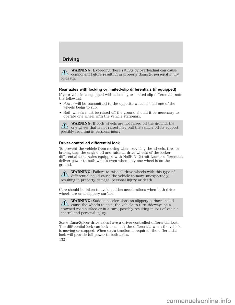
The system is controlled by a switch
located on the instrument panel.
The switch will operate only when
the ignition is in the accessory or on
positions and the air tanks have
sufficient pressure to fill the air
springs. When the ignition is turned
off, the suspension will remain in
whatever state it was last set.
Note:The suspension will dump air when the ignition is in the accessory
or on position, but will only fill when the ignition is in the on position.
When the upper portion of the switch is pressed air supplied to the air
spring is exhausted, lowering the frame for loading. Pressing the lower
portion of the switch causes air to fill the air springs so the vehicle will
remain at normal ride height.
Driving
120
2010 F-650/750(f67)
Supplement(supplement), 1st Printing
USA(fus)
Page 121 of 274

Tractor-trailer connections
WARNING:To reduce the risk of personal injury, use extreme
caution when making brake and light connections. Inclement
weather and accumulated road contamination deposits on handhold
and stepping surfaces require extra care to avoid slip and falls. Provide
adequate lighting of working areas.
WARNING:Do not climb on the back of the tractor unless it
has been provided with a deck plate and handholds. Use a
three-point stance when climbing up and down from a deck plate. Do
not jump from the vehicle. Whenever possible, make all connections
while standing on the ground.
Connecting and disconnecting a trailer with air suspension
When connecting to a trailer:
•Press the lower portion of the switch and air will exhaust from the air
suspension system.
•After making the connection to the trailer, press the upper portion of
the switch, then raise the landing gear.
When disconnecting the trailer:
•Lower the landing gear, then press the lower portion of the switch.
•Disconnect the brake hoses, trailer-side and rear light connectors,
then pull the release lever on the fifth wheel.
The upper portion of the switch must be pressed before operating with a
trailer or operating in the bobtail mode.
Suspension conversions
It is not recommended, or approved, that suspension conversions be
performed. However, it is understood that, on occasion, aftermarket
add-on suspensions are installed by others on the truck chassis which
allow operator control for weight transfer from other axles (i.e., air lift
axles).
WARNING:When operating a loaded vehicle, the driver must
keep all adjustable axles on the ground at all times, supporting
their share of the vehicle’s load. Failure to do so can overload other
axles, tires, wheels, springs, steering components, brakes and frames,
resulting in early component failure, loss of vehicle control, possible
property damage and personal injury.
Driving
121
2010 F-650/750(f67)
Supplement(supplement), 1st Printing
USA(fus)
Page 132 of 274

WARNING:Exceeding these ratings by overloading can cause
component failure resulting in property damage, personal injury
or death.
Rear axles with locking or limited-slip differentials (if equipped)
If your vehicle is equipped with a locking or limited-slip differential, note
the following:
•Power will be transmitted to the opposite wheel should one of the
wheels begin to slip.
•Both wheels must be raised off the ground should it be necessary to
operate one wheel with the vehicle stationary.
WARNING:If both wheels are not raised off the ground, the
one wheel that is not raised may pull the vehicle off its support,
possibly resulting in personal injury
Driver-controlled differential lock
To prevent the vehicle from moving when servicing the wheels, tires or
brakes, turn the engine off and raise all drive wheels of the locker
differential axle. Axles equipped with NoSPIN Detroit Locker differentials
deliver power to both wheels even when only one wheel is on the
ground.
WARNING:Failure to raise all drive wheels with this type of
differential could cause the vehicle to move unexpectedly,
resulting in property damage, personal injury or death.
Care should be taken to avoid sudden accelerations when both drive
wheels are on a slippery surface.
WARNING:Sudden accelerations on slippery surfaces could
cause the wheels to spin, the vehicle to turn sideways on a
crowned road surface or in a turn, possibly resulting in loss of vehicle
control and personal injury.
Some Dana/Spicer drive axles have a driver-controlled differential lock.
The differential lock can lock or unlock the differential when the vehicle
is moving or stopped. When extra traction is required, the differential
lock will provide full power to both axles.
Driving
132
2010 F-650/750(f67)
Supplement(supplement), 1st Printing
USA(fus)
Page 133 of 274

When the differential is locked, the vehicle’s turning radius will increase
(vehicle will “under-steer”)
The differential can be locked or unlocked when the vehicle is moving at
a constant speed of less than 25 mph (40 km/h) and while the wheels
are not slipping. The differential must not be locked when the vehicle is
traveling down steep grades and traction is minimal.
Note:Never use the differential lock at vehicle speeds above 25 mph
(40 km/h).
The differential lock and differential lock light will automatically
disengage at speeds above 25 mph (40 km/h). The differential lock will
remain off until either the vehicle is restarted or the differential lock
switch is turned off then back on.
Axle conversions
It is not recommended, or approved, for axle conversions to be
performed. However, it is understood that, on occasion, aftermarket
add-on axles are installed by others on the truck chassis which allow
operator control for weight transfer from other axles (i.e., air lift axles).
WARNING:When operating a loaded vehicle, the driver must
keep all adjustable axles on the ground at all times, supporting
their share of the vehicle’s load. Failure to do so can overload other
axles, tires, wheels, springs, steering components, brakes and frames,
resulting in early component failure, loss of vehicle control, possible
property damage and personal injury.
TWO-SPEED REAR AXLE (IF EQUIPPED)
A two-speed rear axle allows the driver to select a LO range for greater
pulling power and a HI range for greater road speed and fuel economy.
These ranges can also be used to provide additional steps between
transmission shifts when driving on steep grades and/or fuel economy
may be factors.
Note:Do not shift between ranges when the speed control is on.
WARNING:Never shift a two-speed axle when descending a
steep grade as this may cause loss of vehicle control and result
in personal injury.
Driving
133
2010 F-650/750(f67)
Supplement(supplement), 1st Printing
USA(fus)
Page 136 of 274

MAXIMUM VEHICLE LOADING
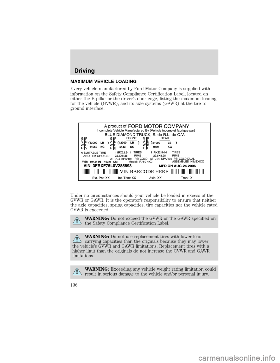
Every vehicle manufactured by Ford Motor Company is supplied with
information on the Safety Compliance Certification Label, located on
either the B-pillar or the driver’s door edge, listing the maximum loading
for the vehicle (GVWR), and its axle systems (GAWR) at the tire to
ground interface.
Under no circumstances should your vehicle be loaded in excess of the
GVWR or GAWR. It is the operator’s responsibility to ensure that neither
the axle capacities, spring capacities, tire capacities nor the vehicle rated
GVWR is exceeded.
WARNING:Do not exceed the GVWR or the GAWR specified on
the Safety Compliance Certification Label.
WARNING:Do not use replacement tires with lower load
carrying capacities than the originals because they may lower
the vehicle’s GVWR and GAWR limitations. Replacement tires with a
higher limit than the originals do not increase the GVWR and GAWR
limitations.
WARNING:Exceeding any vehicle weight rating limitation could
result in serious damage to the vehicle and/or personal injury.
Driving
136
2010 F-650/750(f67)
Supplement(supplement), 1st Printing
USA(fus)