Page 107 of 408

HEADLAMP CONTROL
Turns the lamps off.
Turns on the parking lamps,
instrument panel lamps, license
plate lamps and tail lamps.
Turns the headlamps on.
Autolamp control (if equipped)
The autolamp system provides light
sensitive automatic on-off control of
the exterior lights normally
controlled by the headlamp control.
The autolamp system also keeps the
lights on for approximately
20 seconds. On vehicles equipped
with a message center, you can
select a delay from 0–180 seconds
after the ignition switch is turned to
off.
• To turn autolamps on, rotate the control counterclockwise.
• To turn autolamps off, rotate the control clockwise to the off position.
Fog lamp control (if equipped)
The headlamp control also operates
the fog lamps. The fog lamps can be
turned on only when the headlamp
control is in the , or
position and the high beams are not
turned on.
Pull headlamp control towards you
to turn fog lamps on. The fog lamp
indicator light will illuminate. Lights
107
2010 F-250/350/450/550 (f23)
Owners Guide, 2nd Printing
USA (fus)
Page 108 of 408
Daytime running lamps (DRL) (if equipped)
Turns the headlamps on with a reduced output.
To activate:
• the ignition must be in the on position,
• the headlamp control is in the off or parking lamp position and
• the parking brake must be disengaged.
WARNING: Always remember to turn on your headlamps at
dusk or during inclement weather. The Daytime Running Lamp
(DRL) system does not activate the tail lamps and generally may not
provide adequate lighting during these conditions. Failure to activate
your headlamps under these conditions may result in a collision.
High beams
Push the lever toward the
instrument panel to activate. Pull
the lever toward you to deactivate.
Flash-to-pass
Pull toward you slightly to activate
and release to deactivate. O F F
Lights
108
2010 F-250/350/450/550 (f23)
Owners Guide, 2nd Printing
USA (fus)
Page 109 of 408

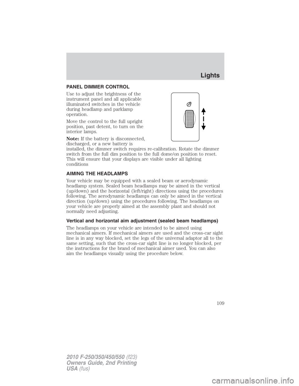
PANEL DIMMER CONTROL
Use to adjust the brightness of the
instrument panel and all applicable
illuminated switches in the vehicle
during headlamp and parklamp
operation.
Move the control to the full upright
position, past detent, to turn on the
interior lamps.
Note: If the battery is disconnected,
discharged, or a new battery is
installed, the dimmer switch requires re-calibration. Rotate the dimmer
switch from the full dim position to the full dome/on position to reset.
This will ensure that your displays are visible under all lighting
conditions
AIMING THE HEADLAMPS
Your vehicle may be equipped with a sealed beam or aerodynamic
headlamp system. Sealed beam headlamps may be aimed in the vertical
(up/down) and the horizontal (left/right) directions using the procedures
following. The aerodynamic headlamps can only be aimed in the vertical
direction (up/down) using the procedures following. The headlamps on
your vehicle are properly aimed at the assembly plant and should not
normally need adjusting.
Vertical and horizontal aim adjustment (sealed beam headlamps)
The headlamps on your vehicle are intended to be aimed using
mechanical aimers. If mechanical aimers are used and the cross-car sight
line is in any way blocked, set the legs of the universal adaptor all to the
same setting, such that the cross-car sight line is no longer blocked, per
the instructions for the brand of mechanical aimer used. You can also
aim the headlamps visually using the procedure below. Lights
109
2010 F-250/350/450/550 (f23)
Owners Guide, 2nd Printing
USA (fus)
Page 113 of 408

MAP LAMPS (IF EQUIPPED)
The dome lamp turns on when:
• any door is opened,
• the instrument panel dimmer
switch is rotated up until the
courtesy lamps come on, and
• any of the remote entry controls
are pressed and the ignition is
off.
BULB REPLACEMENT
Lamp assembly condensation
Exterior lamps are vented to accommodate normal changes in pressure.
Condensation can be a natural by-product of this design. When moist air
enters the lamp assembly through the vents, there is a possibility that
condensation can occur when the temperature is cold. When normal
condensation occurs, a thin film of mist can form on the interior of the
lens. The thin mist eventually clears and exits through the vents during
normal operation. Clearing time may take as long as 48 hours under dry
weather conditions.
Examples of acceptable condensation are:
• Presence of thin mist (no streaks, drip marks or droplets)
• Fine mist covers less than 50% of the lens
Examples of unacceptable moisture (usually caused by a lamp water
leak) are:
• Water puddle inside the lamp
• Large water droplets, drip marks or streaks present on the interior of
the lens
Take your vehicle to dealer for service if any of the above conditions of
unacceptable moisture are present. Lights
113
2010 F-250/350/450/550 (f23)
Owners Guide, 2nd Printing
USA (fus)
Page 114 of 408

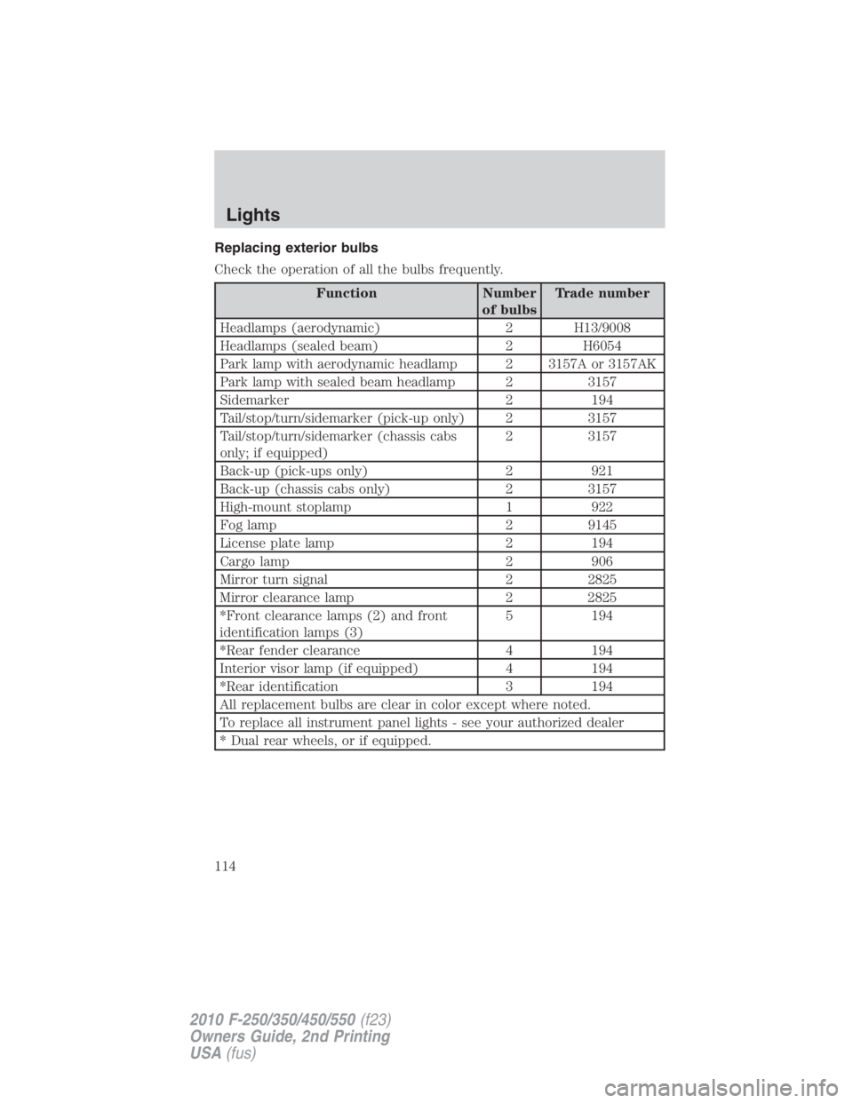
Replacing exterior bulbs
Check the operation of all the bulbs frequently.
Function Number
of bulbs Trade number
Headlamps (aerodynamic) 2 H13/9008
Headlamps (sealed beam) 2 H6054
Park lamp with aerodynamic headlamp 2 3157A or 3157AK
Park lamp with sealed beam headlamp 2 3157
Sidemarker 2 194
Tail/stop/turn/sidemarker (pick-up only) 2 3157
Tail/stop/turn/sidemarker (chassis cabs
only; if equipped) 2 3157
Back-up (pick-ups only) 2 921
Back-up (chassis cabs only) 2 3157
High-mount stoplamp 1 922
Fog lamp 2 9145
License plate lamp 2 194
Cargo lamp 2 906
Mirror turn signal 2 2825
Mirror clearance lamp 2 2825
*Front clearance lamps (2) and front
identification lamps (3) 5 194
*Rear fender clearance 4 194
Interior visor lamp (if equipped) 4 194
*Rear identification 3 194
All replacement bulbs are clear in color except where noted.
To replace all instrument panel lights - see your authorized dealer
* Dual rear wheels, or if equipped.Lights
114
2010 F-250/350/450/550 (f23)
Owners Guide, 2nd Printing
USA (fus)
Page 123 of 408
Center console storage
Use the vehicle’s ignition key to
lock/unlock the compartment.
Under-seat storage
Flip the rear seat cushion up to
access the rear under-seat storage
area. See Seating in the Seating
and Safety Restraints chapter for
more information.
Use the vehicle’s ignition key to
lock/unlock the compartment.
Release the lid latches to open the
storage area.
AUXILIARY POWER POINT (12VDC)
Power outlets are designed for accessory plugs only. Do not insert
any other object in the power outlet for this will damage the
outlet and blow the fuse. Do not hang any type of accessory or
accessory bracket from the plug. Improper use of the power
outlet can cause damage not covered by your warranty.
Auxiliary power points can be found in the following locations:
• On the instrument panel Driver Controls
123
2010 F-250/350/450/550 (f23)
Owners Guide, 2nd Printing
USA (fus)
Page 125 of 408

One-touch down
Allows the driver’s window to open
fully without holding the control
down. Press the switch completely
down to the second detent and
release quickly. The window will
open fully. Momentarily press the
switch to any position to stop the
window operation.
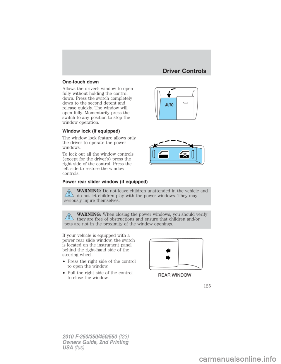
Window lock (if equipped)
The window lock feature allows only
the driver to operate the power
windows.
To lock out all the window controls
(except for the driver’s) press the
right side of the control. Press the
left side to restore the window
controls.
Power rear slider window (if equipped)
WARNING: Do not leave children unattended in the vehicle and
do not let children play with the power windows. They may
seriously injure themselves.
WARNING: When closing the power windows, you should verify
they are free of obstructions and ensure that children and/or
pets are not in the proximity of the window openings.
If your vehicle is equipped with a
power rear slide window, the switch
is located on the instrument panel
behind the right-hand side of the
steering wheel.
• Press the right side of the control
to open the window.
• Pull the right side of the control
to close the window. Driver Controls
125
2010 F-250/350/450/550 (f23)
Owners Guide, 2nd Printing
USA (fus)
Page 137 of 408

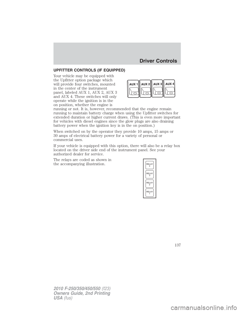
UPFITTER CONTROLS (IF EQUIPPED)
Your vehicle may be equipped with
the Upfitter option package which
will provide four switches, mounted
in the center of the instrument
panel, labeled AUX 1, AUX 2, AUX 3
and AUX 4. These switches will only
operate while the ignition is in the
on position, whether the engine is
running or not. It is, however, recommended that the engine remain
running to maintain battery charge when using the Upfitter switches for
extended duration or higher current draws. (This is even more important
for vehicles with diesel engines since the glow plugs are also draining
battery power when the ignition key is in the on position.)
When switched on by the operator they provide 10 amps, 15 amps or
30 amps of electrical battery power for a variety of personal or
commercial uses.
If your vehicle is equipped with this option, there will also be a relay box
located on the driver side end of the instrument panel. See your
authorized dealer for service.
The relays are coded as shown in
the accompanying illustration. RELAY
1RELAY
2RELAY
3RELAY
4
Driver Controls
137
2010 F-250/350/450/550 (f23)
Owners Guide, 2nd Printing
USA (fus)