Page 108 of 408
Daytime running lamps (DRL) (if equipped)
Turns the headlamps on with a reduced output.
To activate:
• the ignition must be in the on position,
• the headlamp control is in the off or parking lamp position and
• the parking brake must be disengaged.
WARNING: Always remember to turn on your headlamps at
dusk or during inclement weather. The Daytime Running Lamp
(DRL) system does not activate the tail lamps and generally may not
provide adequate lighting during these conditions. Failure to activate
your headlamps under these conditions may result in a collision.
High beams
Push the lever toward the
instrument panel to activate. Pull
the lever toward you to deactivate.
Flash-to-pass
Pull toward you slightly to activate
and release to deactivate. O F F
Lights
108
2010 F-250/350/450/550 (f23)
Owners Guide, 2nd Printing
USA (fus)
Page 113 of 408

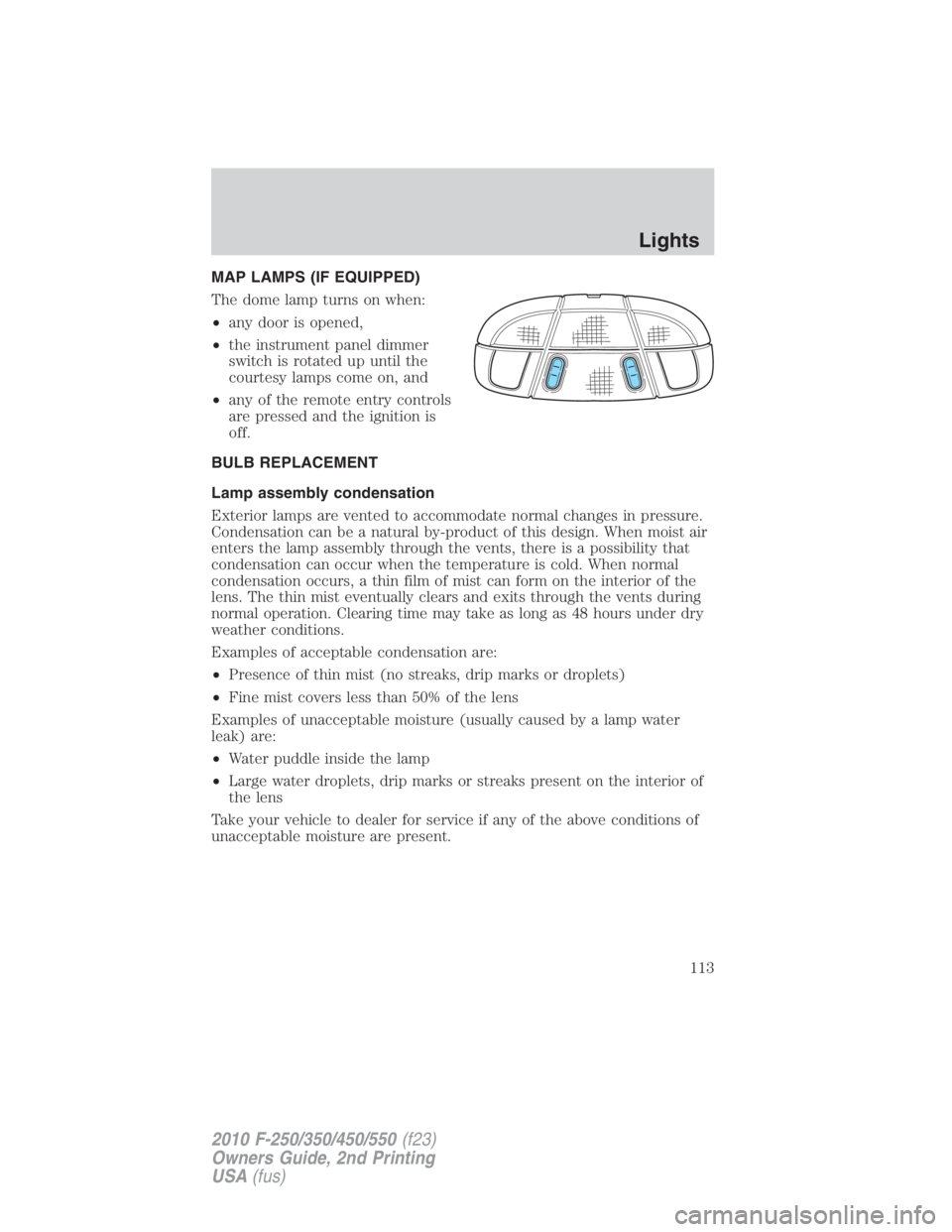
MAP LAMPS (IF EQUIPPED)
The dome lamp turns on when:
• any door is opened,
• the instrument panel dimmer
switch is rotated up until the
courtesy lamps come on, and
• any of the remote entry controls
are pressed and the ignition is
off.
BULB REPLACEMENT
Lamp assembly condensation
Exterior lamps are vented to accommodate normal changes in pressure.
Condensation can be a natural by-product of this design. When moist air
enters the lamp assembly through the vents, there is a possibility that
condensation can occur when the temperature is cold. When normal
condensation occurs, a thin film of mist can form on the interior of the
lens. The thin mist eventually clears and exits through the vents during
normal operation. Clearing time may take as long as 48 hours under dry
weather conditions.
Examples of acceptable condensation are:
• Presence of thin mist (no streaks, drip marks or droplets)
• Fine mist covers less than 50% of the lens
Examples of unacceptable moisture (usually caused by a lamp water
leak) are:
• Water puddle inside the lamp
• Large water droplets, drip marks or streaks present on the interior of
the lens
Take your vehicle to dealer for service if any of the above conditions of
unacceptable moisture are present. Lights
113
2010 F-250/350/450/550 (f23)
Owners Guide, 2nd Printing
USA (fus)
Page 123 of 408
Center console storage
Use the vehicle’s ignition key to
lock/unlock the compartment.
Under-seat storage
Flip the rear seat cushion up to
access the rear under-seat storage
area. See Seating in the Seating
and Safety Restraints chapter for
more information.
Use the vehicle’s ignition key to
lock/unlock the compartment.
Release the lid latches to open the
storage area.
AUXILIARY POWER POINT (12VDC)
Power outlets are designed for accessory plugs only. Do not insert
any other object in the power outlet for this will damage the
outlet and blow the fuse. Do not hang any type of accessory or
accessory bracket from the plug. Improper use of the power
outlet can cause damage not covered by your warranty.
Auxiliary power points can be found in the following locations:
• On the instrument panel Driver Controls
123
2010 F-250/350/450/550 (f23)
Owners Guide, 2nd Printing
USA (fus)
Page 126 of 408

Accessory delay
With accessory delay, the window switches may be used for up to
10 minutes after the ignition switch is turned to the off position or until
either front door is opened.
INTERIOR MIRROR
The interior rear view mirror has two pivot points on the support arm
which lets you adjust the mirror up or down and from side to side.
WARNING: Do not adjust the mirror while the vehicle is in
motion.
Automatic dimming interior rear view mirror (if equipped)
Your vehicle may be equipped with an interior rear view mirror which
has an auto-dimming function. The electronic day/night mirror will
change from the normal (high reflective) state to the non-glare
(darkened) state when bright lights (glare) reach the mirror. When the
mirror detects bright light from behind the vehicle, it will automatically
adjust (darken) to minimize glare.
The mirror will automatically return to the normal state whenever the
vehicle is placed in R (Reverse) to ensure a bright clear view when
backing up.
Do not block the sensors on the front and back of the interior
rear view mirror since this may impair proper mirror
performance.
Do not clean the housing or glass of any mirror with harsh
abrasives, fuel or other petroleum-based cleaning products.
Note: If equipped with a rearview camera system, a video image will be
displayed in the mirror or the navigation system (if equipped) when the
vehicle is put in R (Reverse). As you shift into any other gear from R
(Reverse), the image will remain for a few seconds and then turn off.
Refer to Rearview camera system in the Driving chapter.Driver Controls
126
2010 F-250/350/450/550 (f23)
Owners Guide, 2nd Printing
USA (fus)
Page 134 of 408
Turning off speed control
There are two ways to turn off the speed control:
• Depress the brake pedal. This will not erase your vehicle’s previously
set speed.
• Press the speed control OFF
control.
Note: When you turn off the speed
control or the ignition, your speed
control set speed memory is erased.
STEERING WHEEL CONTROLS (IF EQUIPPED)
These controls allow you to operate some radio and climate control
features.
Audio control features
Press MEDIA to select:
• AM, FM1, FM2
• CD (if equipped)
• DVD (if equipped)
• SAT1, SAT2 or SAT3 (Satellite
Radio mode, if equipped).
• LINE IN (Auxiliary input jack)Driver Controls
134
2010 F-250/350/450/550 (f23)
Owners Guide, 2nd Printing
USA (fus)
Page 137 of 408

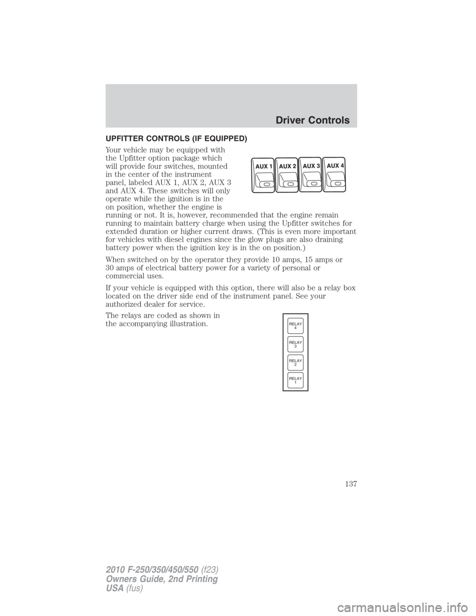
UPFITTER CONTROLS (IF EQUIPPED)
Your vehicle may be equipped with
the Upfitter option package which
will provide four switches, mounted
in the center of the instrument
panel, labeled AUX 1, AUX 2, AUX 3
and AUX 4. These switches will only
operate while the ignition is in the
on position, whether the engine is
running or not. It is, however, recommended that the engine remain
running to maintain battery charge when using the Upfitter switches for
extended duration or higher current draws. (This is even more important
for vehicles with diesel engines since the glow plugs are also draining
battery power when the ignition key is in the on position.)
When switched on by the operator they provide 10 amps, 15 amps or
30 amps of electrical battery power for a variety of personal or
commercial uses.
If your vehicle is equipped with this option, there will also be a relay box
located on the driver side end of the instrument panel. See your
authorized dealer for service.
The relays are coded as shown in
the accompanying illustration. RELAY
1RELAY
2RELAY
3RELAY
4
Driver Controls
137
2010 F-250/350/450/550 (f23)
Owners Guide, 2nd Printing
USA (fus)
Page 140 of 408

current U.S. federal safety standards. For more information, contact
HomeLink � at: www.homelink.com or 1–800–355–3515.
Retain the original transmitter for use in other vehicles as well as for
future programming procedures (i.e. new HomeLink � equipped vehicle
purchase). It is also suggested that upon the sale of the vehicle, the
programmed Homelink � buttons be erased for security purposes, refer to
Programming in this section.
Programming
Do not program HomeLink � with the vehicle parked in the garage.
Note: Your vehicle may require the ignition switch to be turned to the
accessory position for programming and/or operation of the HomeLink � .
It is also recommended that a new battery be placed in the hand-held
transmitter of the device being programmed to HomeLink � for quicker
training and accurate transmission of the radio-frequency signal.
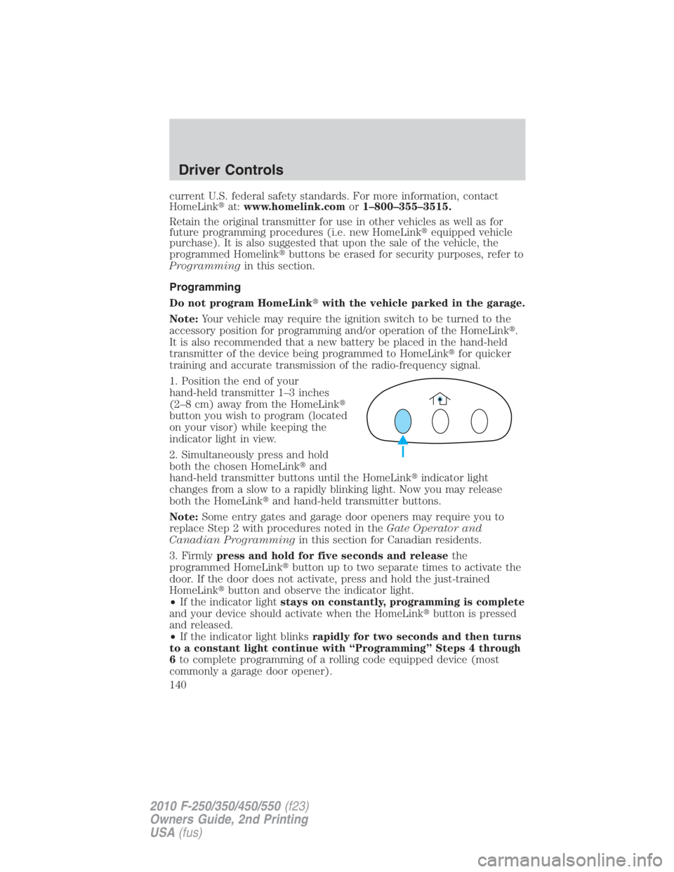
1. Position the end of your
hand-held transmitter 1–3 inches
(2–8 cm) away from the HomeLink �
button you wish to program (located
on your visor) while keeping the
indicator light in view.
2. Simultaneously press and hold
both the chosen HomeLink � and
hand-held transmitter buttons until the HomeLink � indicator light
changes from a slow to a rapidly blinking light. Now you may release
both the HomeLink � and hand-held transmitter buttons.
Note: Some entry gates and garage door openers may require you to
replace Step 2 with procedures noted in the Gate Operator and
Canadian Programming in this section for Canadian residents.
3. Firmly press and hold for five seconds and release the
programmed HomeLink � button up to two separate times to activate the
door. If the door does not activate, press and hold the just-trained
HomeLink � button and observe the indicator light.
• If the indicator light stays on constantly, programming is complete
and your device should activate when the HomeLink � button is pressed
and released.
• If the indicator light blinks rapidly for two seconds and then turns
to a constant light continue with “Programming” Steps 4 through
6 to complete programming of a rolling code equipped device (most
commonly a garage door opener).Driver Controls
140
2010 F-250/350/450/550 (f23)
Owners Guide, 2nd Printing
USA (fus)
Page 143 of 408

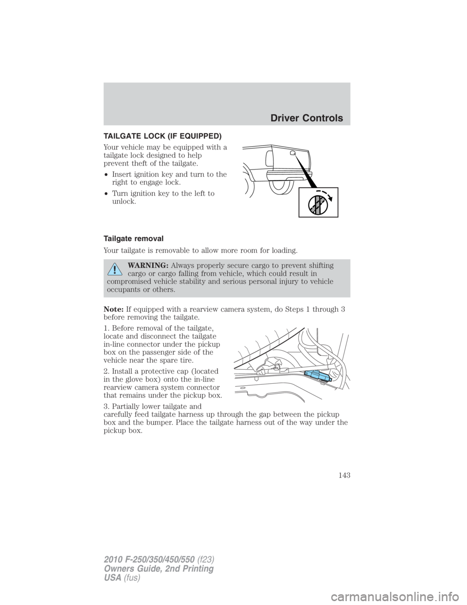
TAILGATE LOCK (IF EQUIPPED)
Your vehicle may be equipped with a
tailgate lock designed to help
prevent theft of the tailgate.
• Insert ignition key and turn to the
right to engage lock.
• Turn ignition key to the left to
unlock.
Tailgate removal
Your tailgate is removable to allow more room for loading.
WARNING: Always properly secure cargo to prevent shifting
cargo or cargo falling from vehicle, which could result in
compromised vehicle stability and serious personal injury to vehicle
occupants or others.
Note: If equipped with a rearview camera system, do Steps 1 through 3
before removing the tailgate.
1. Before removal of the tailgate,
locate and disconnect the tailgate
in-line connector under the pickup
box on the passenger side of the
vehicle near the spare tire.
2. Install a protective cap (located
in the glove box) onto the in-line
rearview camera system connector
that remains under the pickup box.
3. Partially lower tailgate and
carefully feed tailgate harness up through the gap between the pickup
box and the bumper. Place the tailgate harness out of the way under the
pickup box. Driver Controls
143
2010 F-250/350/450/550 (f23)
Owners Guide, 2nd Printing
USA (fus)