Page 256 of 344
Fuse/Relay
LocationFuse Amp
RatingProtected Circuits
5 5A Moon roof, Power down back
window, Door lock switch
illumination, Auto dimming rear
view mirror
6 20A Door unlock/lock
7 15A Trailer tow stop/turn lamps
8 15A Ignition switch power, Passive
anti-theft system (PATS), Cluster
9 2A 6-speed Transmission control
module/Powertrain control
module (Ignition RUN/START),
Fuel pump relay
10 5A Front wiper RUN/ACC relay in
power distribution box (PDB)
11 5A Radio start
12 5A Radio, Trailer tow battery charge
(relay in PDB)
13 15A Heated mirror
14 20A Horn
15 10A Reverse lamps
16 10A Trailer tow reverse lamps
17 10A Restraints control module,
Passenger occupancy
18 10A Roll Stability Control™ (RSC�)
switch, RSC�, 4x4 module, 4x4
switch, Heated seat switches,
Reverse park aid
19 — Not used
20 10A Climate control system, Brake
shift
21 — Not used
Roadside Emergencies
256
2010 07+ Explorer Sport Trac(esp)
Owners Guide(own2002), 1st Printing
USA(fus)
Page 257 of 344

Fuse/Relay
LocationFuse Amp
RatingProtected Circuits
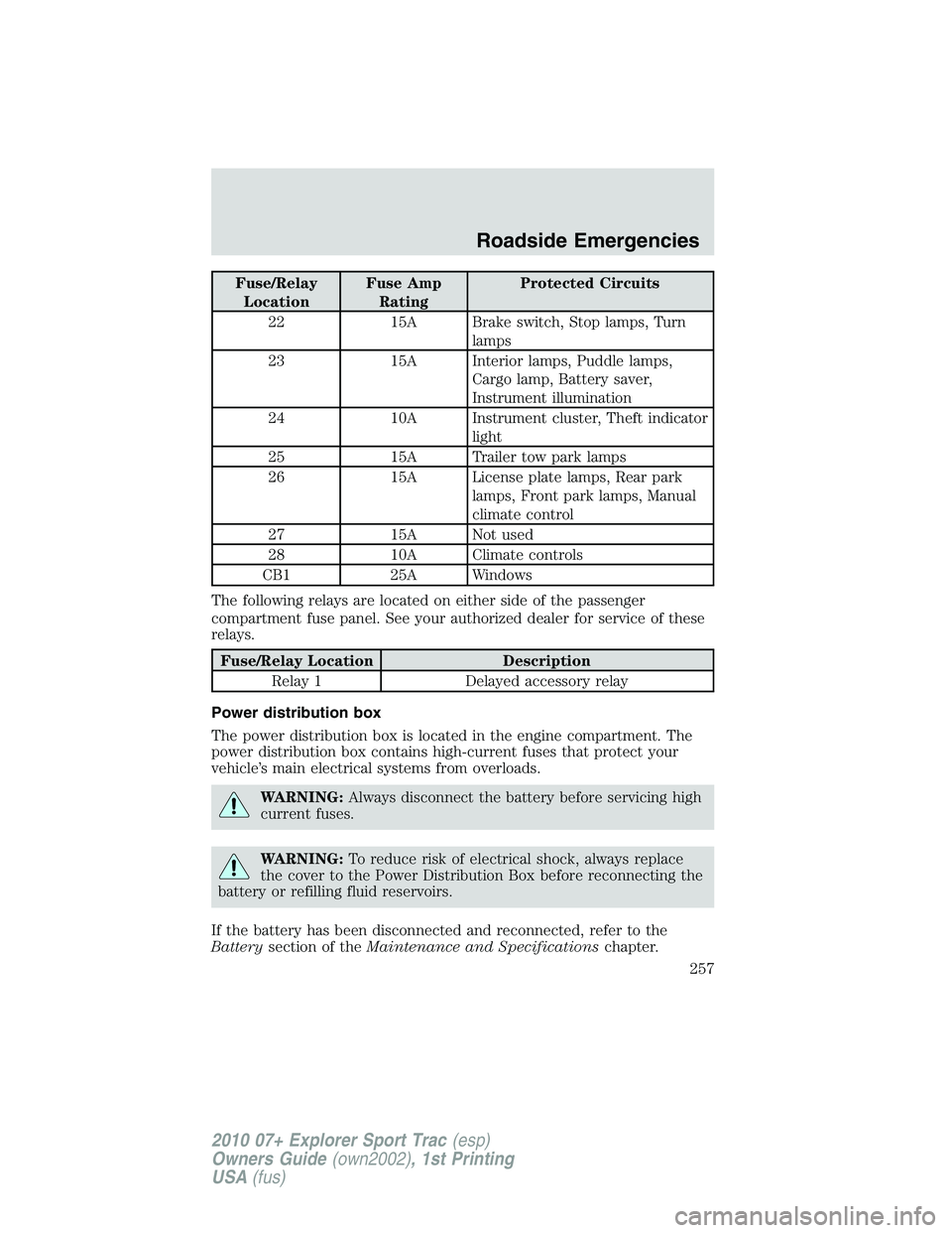
22 15A Brake switch, Stop lamps, Turn
lamps
23 15A Interior lamps, Puddle lamps,
Cargo lamp, Battery saver,
Instrument illumination
24 10A Instrument cluster, Theft indicator
light
25 15A Trailer tow park lamps
26 15A License plate lamps, Rear park
lamps, Front park lamps, Manual
climate control
27 15A Not used
28 10A Climate controls
CB1 25A Windows
The following relays are located on either side of the passenger
compartment fuse panel. See your authorized dealer for service of these
relays.
Fuse/Relay Location Description
Relay 1 Delayed accessory relay
Power distribution box
The power distribution box is located in the engine compartment. The
power distribution box contains high-current fuses that protect your
vehicle’s main electrical systems from overloads.
WARNING:Always disconnect the battery before servicing high
current fuses.
WARNING:To reduce risk of electrical shock, always replace
the cover to the Power Distribution Box before reconnecting the
battery or refilling fluid reservoirs.
If the battery has been disconnected and reconnected, refer to the
Batterysection of theMaintenance and Specificationschapter.
Roadside Emergencies
257
2010 07+ Explorer Sport Trac(esp)
Owners Guide(own2002), 1st Printing
USA(fus)
Page 258 of 344
The high-current fuses are coded as follows:
Fuse/Relay
LocationFuse Amp
RatingProtected Circuits
1 50A** Battery feed 2 (passenger
compartment fuse panel)
2 50A** Battery feed 3 (passenger
compartment fuse panel)
3 50A** Battery feed 1 (passenger
compartment fuse panel)
4 30A** Fuel pump, Fuel injectors
5 — Not used
6 40A** Anti-lock brake system (ABS) pump
7 40A** Powertrain control module (PCM)
8 — Not used
9 — Not used
10 20A** Power down back window
11 30A** Starter
12 — Not used
Roadside Emergencies
258
2010 07+ Explorer Sport Trac(esp)
Owners Guide(own2002), 1st Printing
USA(fus)
Page 259 of 344
Fuse/Relay
LocationFuse Amp
RatingProtected Circuits
13 30A** Trailer tow battery charge
14 40A ** Power drivers seat
15 40A** Heated mirror
16 40A** Blower motor
17 30A** Trailer tow electronic brakes
18 — Not used
19 — Not used
20 30A** Front wiper motor
21 20A* Rear of console power point
22 20A* Subwoofer
23 20A* 4x4 module
24 10A* PCM – keep alive power, Canister
vent
25 20A* Front of console power point/Cigar
lighter
26 20A* 4x4 module, All wheel drive (AWD)
module
27 20A* 6–speed transmission control
module (TCM) (4.6L engine only)
28 20A* Heated seats
29 15A* Right high/low beam headlamp
30 20A* Cargo bed power point
31 15A* Fog lamps
32 5A* Power mirrors
33 30A* ABS valves
34 15A* Left high/low beam headlamp
35 10A* A/C clutch
36 20A* Console bin power point
37 30A* Driver window motor
38 15A* 5–speed transmission (4.0L engine
only)
39 15A* PCM power
Roadside Emergencies
259
2010 07+ Explorer Sport Trac(esp)
Owners Guide(own2002), 1st Printing
USA(fus)
Page 260 of 344
Fuse/Relay
LocationFuse Amp
RatingProtected Circuits
40 15A* Fan clutch, Positive crackcase
ventilation (PCV) valve, A/C clutch
relay
41 15A* Satellite radio module, SYNC�
42 15A* Speed control deactivation switch,
Electronic vapor management valve,
Mass air flow sensor, Heated
exhaust gas oxygen (HEGO) sensor,
EVR, CMS, Variable cam timing
(VCT)1, VCT2, CMCV on 4.6L only)
43 15A* Coil on plug (4.6L engine), Coil
tower (4.0L engine)
44 15A* Fuel injectors
45B — Not used
45A — Not used
46B — Not used
46A — Not used
49 — Fuel pump relay
50B — A/C clutch relay
50A — Fog lamps relay
51 — Not used
52 — Not used
53 — One touch integrated start (OTIS)
(diode)
54 — Trailer tow battery charge relay
55B — Front wiper relay
55A — PCM relay
56B — Starter relay
56A — Climate control blower relay
* Mini Fuses ** Cartridge Fuses
Roadside Emergencies
260
2010 07+ Explorer Sport Trac(esp)
Owners Guide(own2002), 1st Printing
USA(fus)
Page 270 of 344

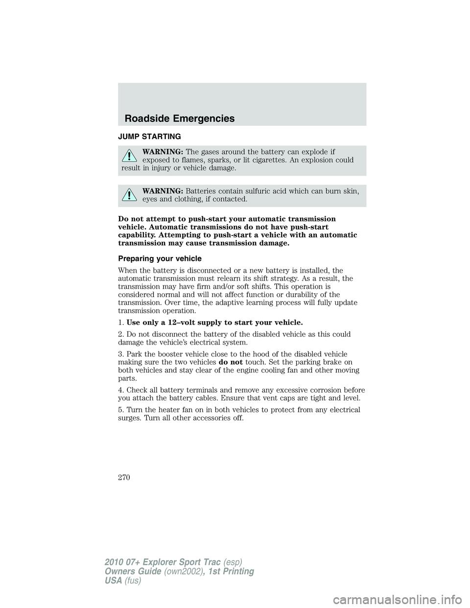
JUMP STARTING
WARNING:The gases around the battery can explode if
exposed to flames, sparks, or lit cigarettes. An explosion could
result in injury or vehicle damage.
WARNING:Batteries contain sulfuric acid which can burn skin,
eyes and clothing, if contacted.
Do not attempt to push-start your automatic transmission
vehicle. Automatic transmissions do not have push-start
capability. Attempting to push-start a vehicle with an automatic
transmission may cause transmission damage.
Preparing your vehicle
When the battery is disconnected or a new battery is installed, the
automatic transmission must relearn its shift strategy. As a result, the
transmission may have firm and/or soft shifts. This operation is
considered normal and will not affect function or durability of the
transmission. Over time, the adaptive learning process will fully update
transmission operation.
1.Use only a 12–volt supply to start your vehicle.
2. Do not disconnect the battery of the disabled vehicle as this could
damage the vehicle’s electrical system.
3. Park the booster vehicle close to the hood of the disabled vehicle
making sure the two vehiclesdo nottouch. Set the parking brake on
both vehicles and stay clear of the engine cooling fan and other moving
parts.
4. Check all battery terminals and remove any excessive corrosion before
you attach the battery cables. Ensure that vent caps are tight and level.
5. Turn the heater fan on in both vehicles to protect from any electrical
surges. Turn all other accessories off.
Roadside Emergencies
270
2010 07+ Explorer Sport Trac(esp)
Owners Guide(own2002), 1st Printing
USA(fus)
Page 271 of 344
Connecting the jumper cables
1. Connect the positive (+) jumper cable to the positive (+) terminal of
the discharged battery.
Note:In the illustrations,lightning boltsare used to designate the
assisting (boosting) battery.
2. Connect the other end of the positive (+) cable to the positive (+)
terminal of the assisting battery.
+–+–
+–+–
Roadside Emergencies
271
2010 07+ Explorer Sport Trac(esp)
Owners Guide(own2002), 1st Printing
USA(fus)
Page 272 of 344
3. Connect the negative (-) cable to the negative (-) terminal of the
assisting battery.
4. Make the final connection of the negative (-) cable to the ground stud
located toward the front of the vehicle (forward of the battery) on the
radiator support. Keep the negative (-) cable away from the battery and
the carburetor/fuel injection system.
+–+–
++-
-
Roadside Emergencies
272
2010 07+ Explorer Sport Trac(esp)
Owners Guide(own2002), 1st Printing
USA(fus)