2010 FORD EXPEDITION instrument cluster
[x] Cancel search: instrument clusterPage 298 of 420
During trailer sway control events the “sliding car”icon in the
instrument cluster will flash momentarily. The cluster message center
will also displayTRAILER SWAY REDUCE SPEED. In some cases
when trailer sway is detected, the vehicle speed is too high and may be
above a speed at which trailer sway will not grow continuously. This may
cause the system to activate multiple times, causing a gradual reduction
in speed.
Note:The trailer sway control will only activate at speeds greater than
40 mph (64 km/h).
Disabling Trailer Sway Control
Trailer sway control can be disabled during any key cycle. SeeMessage
centerin theInstrument Clusterchapter. Note that regardless of
chosen enable state, trailer sway control will be re-enabled at each new
key cycle.
WARNING:Turning off trailer sway control increases the risk of
loss of vehicle control, serious injury, or death. Ford does not
recommend disabling this feature except in situations where speed
reduction may be detrimental (e.g., hill climbing), the driver has
significant trailer towing experience, and can control trailer sway and
maintain safe operation.
STEERING
Your vehicle is equipped with power steering. Power steering uses energy
from the engine to decrease the driver’s effort in steering the vehicle.
To help prevent damage to the power steering pump:
•Never hold the steering wheel to the extreme right or the extreme left
for more than a few seconds when the engine is running.
•Do not operate the vehicle with the power steering pump fluid level
below the MIN mark on the reservoir.
•Some noise is normal during operation. If the noise is excessive, check
for low power steering pump fluid level before seeking service by your
authorized dealer.
•Heavy or uneven steering efforts may be caused by low power steering
pump fluid level. Check for low power steering pump fluid level before
seeking service by your authorized dealer.
•Do not fill the power steering pump reservoir above the MAX mark on
the reservoir, as this may result in leaks from the reservoir.
Driving
298
2010 Expedition(exd)
Owners Guide(own2002), 1st Printing
USA(fus)
Page 299 of 420
If the power steering system breaks down (or if the engine is turned
off), you can steer the vehicle manually, but it takes more effort.
If the steering wanders or pulls, check for:
•Underinflated tire(s) on any wheel(s)
•Uneven vehicle loading
•High crown in center of road
•High crosswinds
•Wheels out of alignment
•Loose or worn suspension components
Variable assist steering
Your vehicle is equipped with variable assist power steering. At low
engine RPM, steering assist will adjust to reduce efforts and improve low
speed maneuverability. At high engine RPM, the assist will adjust to
improve steering feel at high speeds.
If the amount of effort required to steer your vehicle changes while
driving at a constant engine RPM, have the power steering system
checked by your authorized dealer.
AIR SUSPENSION SYSTEM (IF EQUIPPED)
The air suspension system is designed to improve ride, handling and
general vehicle performance during:
•Certain road conditions
•Steering maneuvers
•Braking
•Acceleration
This system keeps the rear of your vehicle at a constant level by
automatically adding air or releasing air from the springs. If you exceed
the load limit, the rear air suspension may not operate. The air
suspension system will stay active for 40 minutes after the ignition is
turned off to accommodate any load changes. (The air compressor may
run when the vehicle is off; this is normal.)
The air suspension system can be enabled or disabled through the
message center. Refer toMessage centerin theInstrument cluster
chapter.
Driving
299
2010 Expedition(exd)
Owners Guide(own2002), 1st Printing
USA(fus)
Page 306 of 420
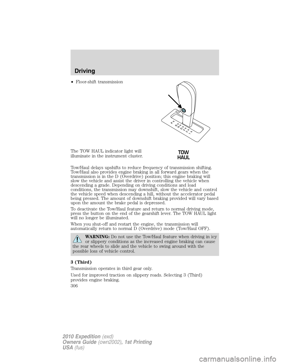
•Floor-shift transmission
The TOW HAUL indicator light will
illuminate in the instrument cluster.
Tow/Haul delays upshifts to reduce frequency of transmission shifting.
Tow/Haul also provides engine braking in all forward gears when the
transmission is in the D (Overdrive) position; this engine braking will
slow the vehicle and assist the driver in controlling the vehicle when
descending a grade. Depending on driving conditions and load
conditions, the transmission may downshift, slow the vehicle and control
the vehicle speed when descending a hill, without the accelerator pedal
being pressed. The amount of downshift braking provided will vary based
upon the amount the brake pedal is depressed.
To deactivate the Tow/Haul feature and return to normal driving mode,
press the button on the end of the gearshift lever. The TOW HAUL light
will no longer be illuminated.
When you shut-off and restart the engine, the transmission will
automatically return to normal D (Overdrive) mode (Tow/Haul OFF).
WARNING:Do not use the Tow/Haul feature when driving in icy
or slippery conditions as the increased engine braking can cause
the rear wheels to slide and the vehicle to swing around with the
possible loss of vehicle control.
3 (Third)
Transmission operates in third gear only.
Used for improved traction on slippery roads. Selecting 3 (Third)
provides engine braking.
Driving
306
2010 Expedition(exd)
Owners Guide(own2002), 1st Printing
USA(fus)
Page 309 of 420
While receiving a warning the radio volume will be reduced to a
predetermined level. After the warning goes away, the radio will return
to the previous value.
Audible Warnings
Distance to Object Warning
Speed above 2.5 mph (4 km/h)
up to 1.6 feet (.5 meters) Solid
1.6 feet (.5 meters) to 3.1 feet
(1 meter)Fast beep
3.1 feet (1 meter) to 5.7 feet
(1.8 meters)Medium/fast beep
5.7 feet (1.8 meters) to 9 feet
(2.8 meters)Medium beep
9 feet (2.8 meters) to 13 feet
(4 meters)Medium/slow beep
13 feet (4 meters) to 19.6 feet
(6 meters)Slow beep
Speed below 2.5 mph (4 km/h)
up to 1.4 feet (.4 meters) Solid
1.4 feet (.4 meters) to 3 feet
(.9 meters)Fast beep
3 feet (.9 meters) to 4.5 feet
(1.4 meters)Medium beep
4.5 feet (1.4 meters) to
6.3 feet (1.9 meters)Medium/slow beep
6.3 feet (1.9 meters) to
8.7 feet (2.6 meters)Slow beep
8.7 feet (2.6 meters) to
16.4 feet (5 meters)No sound
The reverse sensing system is automatically enabled when the gearshift
lever is placed in R (Reverse) and the ignition is on. A control in the
message center allows the driver to disable the system, refer toMessage
centerin theInstrument Clusterchapter for more information.
Note:If the system cannot be turned off, refer toMyKeyin theLocks
and Securitychapter for more information.
Driving
309
2010 Expedition(exd)
Owners Guide(own2002), 1st Printing
USA(fus)
Page 313 of 420
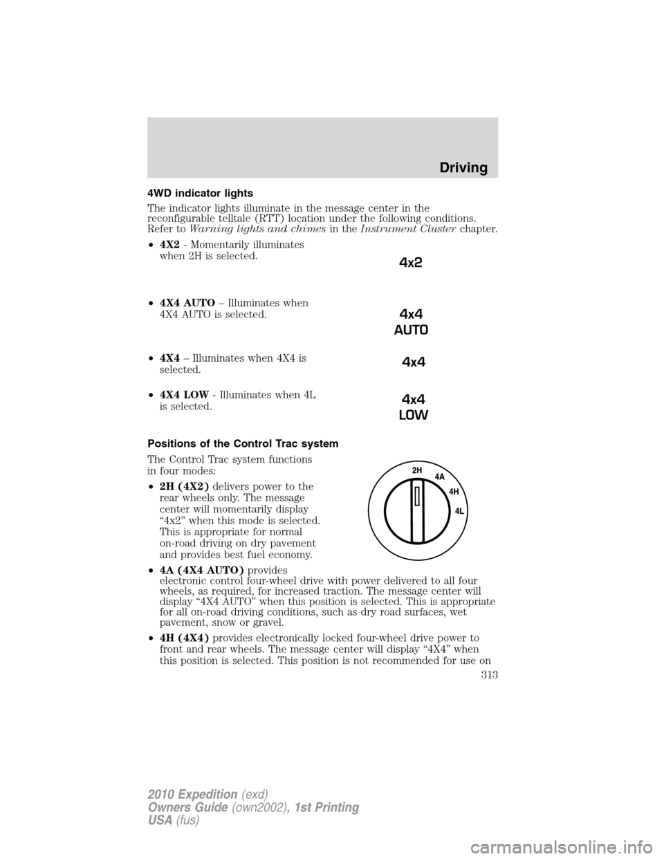
4WD indicator lights
The indicator lights illuminate in the message center in the
reconfigurable telltale (RTT) location under the following conditions.
Refer toWarning lights and chimesin theInstrument Clusterchapter.
•4X2- Momentarily illuminates
when 2H is selected.
•4X4 AUTO– Illuminates when
4X4 AUTO is selected.
•4X4– Illuminates when 4X4 is
selected.
•4X4 LOW- Illuminates when 4L
is selected.
Positions of the Control Trac system
The Control Trac system functions
in four modes:
•2H (4X2)delivers power to the
rear wheels only. The message
center will momentarily display
“4x2” when this mode is selected.
This is appropriate for normal
on-road driving on dry pavement
and provides best fuel economy.
•4A (4X4 AUTO)provides
electronic control four-wheel drive with power delivered to all four
wheels, as required, for increased traction. The message center will
display “4X4 AUTO” when this position is selected. This is appropriate
for all on-road driving conditions, such as dry road surfaces, wet
pavement, snow or gravel.
•4H (4X4)provides electronically locked four-wheel drive power to
front and rear wheels. The message center will display “4X4” when
this position is selected. This position is not recommended for use on
4x2
4x4
AUTO
4x4
4x4
LOW
Driving
313
2010 Expedition(exd)
Owners Guide(own2002), 1st Printing
USA(fus)
Page 330 of 420

Fuse/Relay
LocationFuse Amp
RatingProtected Circuits
23 15A High beam headlamps
24 20A Horn
25 10A Demand lamps, Glovebox, Visor
26 10A Instrument panel cluster
27 20A Ignition switch
28 5A Radio
29 5A Instrument panel cluster
30 5A Not used (spare)
31 10A Not used (spare)
32 10A Airbag module
33 10A Not used (spare)
34 5A Not used (spare)
35 10A Rear park assist, 4x4, rear video
camera
36 5A Passive anti-theft system
37 10A Climate control
38 20A Subwoofer
39 20A Radio
40 20A Navigation system
41 15A Power windows, Power vents,
Power moon roof, Auto dimming
rear view mirror
42 10A Not used (spare)
43 10A Rear wiper logic, Rain sensor
44 10A Trailer tow battery charge relay
coil
45 5A Front wiper logic
46 7.5A Climate control, Auxiliary relay
control
47 30A Circuit
BreakerPower windows, Moon roof
48 — Delayed accessory relay
Roadside Emergencies
330
2010 Expedition(exd)
Owners Guide(own2002), 1st Printing
USA(fus)
Page 339 of 420
Tire change procedure
WARNING:To help prevent the vehicle from moving when you
change a tire, be sure the parking brake is set, then block the
wheels (both front or both rear) on the opposite end of the vehicle
from the wheel being changed. If on a grade, block both opposite
wheels on the downward side of the hill.
WARNING:If the vehicle slips off the jack, you or someone else
could be seriously injured.
WARNING:On vehicles equipped with air suspension, turn off
the Air Suspension system prior to jacking, hoisting or towing
your vehicle.
WARNING:Turn off the running boards (if equipped) before
jacking or placing any object under the vehicle. Never place your
hand between the extended running board and the vehicle. A moving
running board may cause injury.
WARNING:Do not attempt to change a tire on the side of the
vehicle close to moving traffic. Pull far enough off the road to
avoid the danger of being hit when operating the jack and changing the
wheel.
Note:Passengers should not remain in the vehicle when the vehicle is
being jacked.
If your vehicle is equipped with air suspension, refer toMessage center
in theInstrument Clusterchapter for instructions on turning the air
suspension system off.
Refer to the instruction sheet (located in the rear floor compartment
behind the 3rd row seat with the jack tray tools assembly kit) for
detailed tire change instructions.
Roadside Emergencies
339
2010 Expedition(exd)
Owners Guide(own2002), 1st Printing
USA(fus)
Page 340 of 420
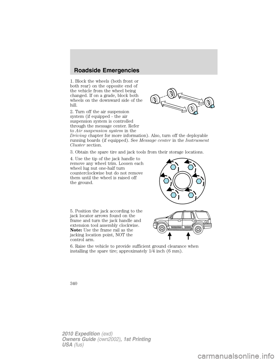
1. Block the wheels (both front or
both rear) on the opposite end of
the vehicle from the wheel being
changed. If on a grade, block both
wheels on the downward side of the
hill.
2. Turn off the air suspension
system (if equipped - the air
suspension system is controlled
through the message center. Refer
toAir suspension systemin the
Drivingchapter for more information). Also, turn off the deployable
running boards (if equipped). SeeMessage centerin theInstrument
Clustersection.
3. Obtain the spare tire and jack tools from their storage locations.
4. Use the tip of the jack handle to
remove any wheel trim. Loosen each
wheel lug nut one-half turn
counterclockwise but do not remove
them until the wheel is raised off
the ground.
5. Position the jack according to the
jack locator arrows found on the
frame and turn the jack handle and
extension tool assembly clockwise.
Note:Use the frame rail as the
jacking location point, NOT the
control arm.
6. Raise the vehicle to provide sufficient ground clearance when
installing the spare tire; approximately 1/4 inch (6 mm).
Roadside Emergencies
340
2010 Expedition(exd)
Owners Guide(own2002), 1st Printing
USA(fus)