2010 FORD EXPEDITION clock
[x] Cancel search: clockPage 135 of 420

EXTERIOR MIRRORS
Power side view mirrors
The ignition can be in any position to adjust the power side view mirrors.
To adjust your mirrors:
1. Rotate the control clockwise to
adjust the right mirror and rotate
the control counterclockwise to
adjust the left mirror.
2. Move the control in the direction
you wish to tilt the mirror.
3. Return to the center position to
lock mirrors in place.
Memory feature (if equipped)
The power side view mirror positions are saved when doing a memory
set function and can be recalled along with the vehicle personality
features when a memory position is selected through the remote entry
transmitter, keyless entry keypad or memory switch on the driver’s door.
Refer toSeatingin theSeating and Safety Restraintschapter.
Fold-away mirrors
Fold the side mirrors in carefully
before driving through a narrow
space, like an automatic car wash.
Powerfold mirrors (if equipped)
Rotate the 4–way adjustment switch
to the center position. Press the
switch down to auto fold in and
down again to auto fold back to
design position. Powerfold the side
mirrors in carefully when driving
through a narrow space, like an automatic car wash.
The mirrors may be moved inward/outward manually. If a mirror is
moved manually, it will need to be reset. To reset: with the switch in the
center position, press the switch down to fold the mirrors in and wait a
short period (eight seconds). An audible “click” will be heard indicating
re-synchronization. If the click is not heard, use the switch to fold the
mirrors out, then in, until the click is heard. After that, the mirrors will
operate to their normal positions until they are again moved manually.
POWER FOLD
Driver Controls
135
2010 Expedition(exd)
Owners Guide(own2002), 1st Printing
USA(fus)
Page 187 of 420
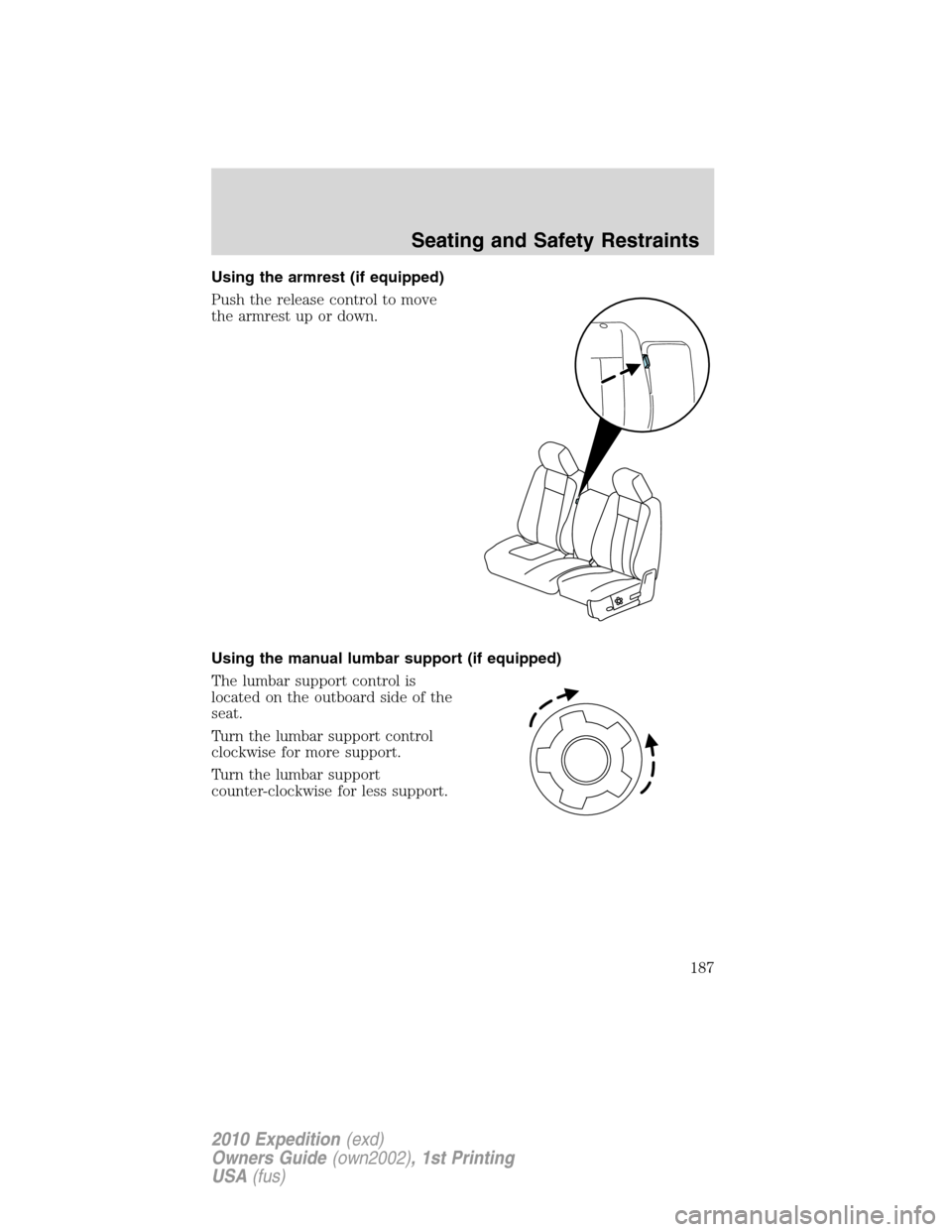
Using the armrest (if equipped)
Push the release control to move
the armrest up or down.
Using the manual lumbar support (if equipped)
The lumbar support control is
located on the outboard side of the
seat.
Turn the lumbar support control
clockwise for more support.
Turn the lumbar support
counter-clockwise for less support.
Seating and Safety Restraints
187
2010 Expedition(exd)
Owners Guide(own2002), 1st Printing
USA(fus)
Page 338 of 420
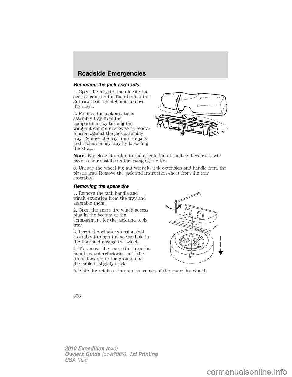
Removing the jack and tools
1. Open the liftgate, then locate the
access panel on the floor behind the
3rd row seat. Unlatch and remove
the panel.
2. Remove the jack and tools
assembly tray from the
compartment by turning the
wing-nut counterclockwise to relieve
tension against the jack assembly
tray. Remove the bag from the jack
and tool assembly tray by loosening
the strap.
Note:Pay close attention to the orientation of the bag, because it will
have to be reinstalled after changing the tire.
3. Unsnap the wheel lug nut wrench, jack extension and handle from the
plastic tray. Remove the jack and instruction sheet from the tray
assembly.
Removing the spare tire
1. Remove the jack handle and
winch extension from the tray and
assemble them.
2. Open the spare tire winch access
plug in the bottom of the
compartment for the jack and tools
tray.
3. Insert the winch extension tool
assembly through the access hole in
the floor and engage the winch.
4. To remove the spare tire, turn the
handle counterclockwise until the
tire is lowered to the ground and
the cable is slightly slack.
5. Slide the retainer through the center of the spare tire wheel.
Roadside Emergencies
338
2010 Expedition(exd)
Owners Guide(own2002), 1st Printing
USA(fus)
Page 340 of 420
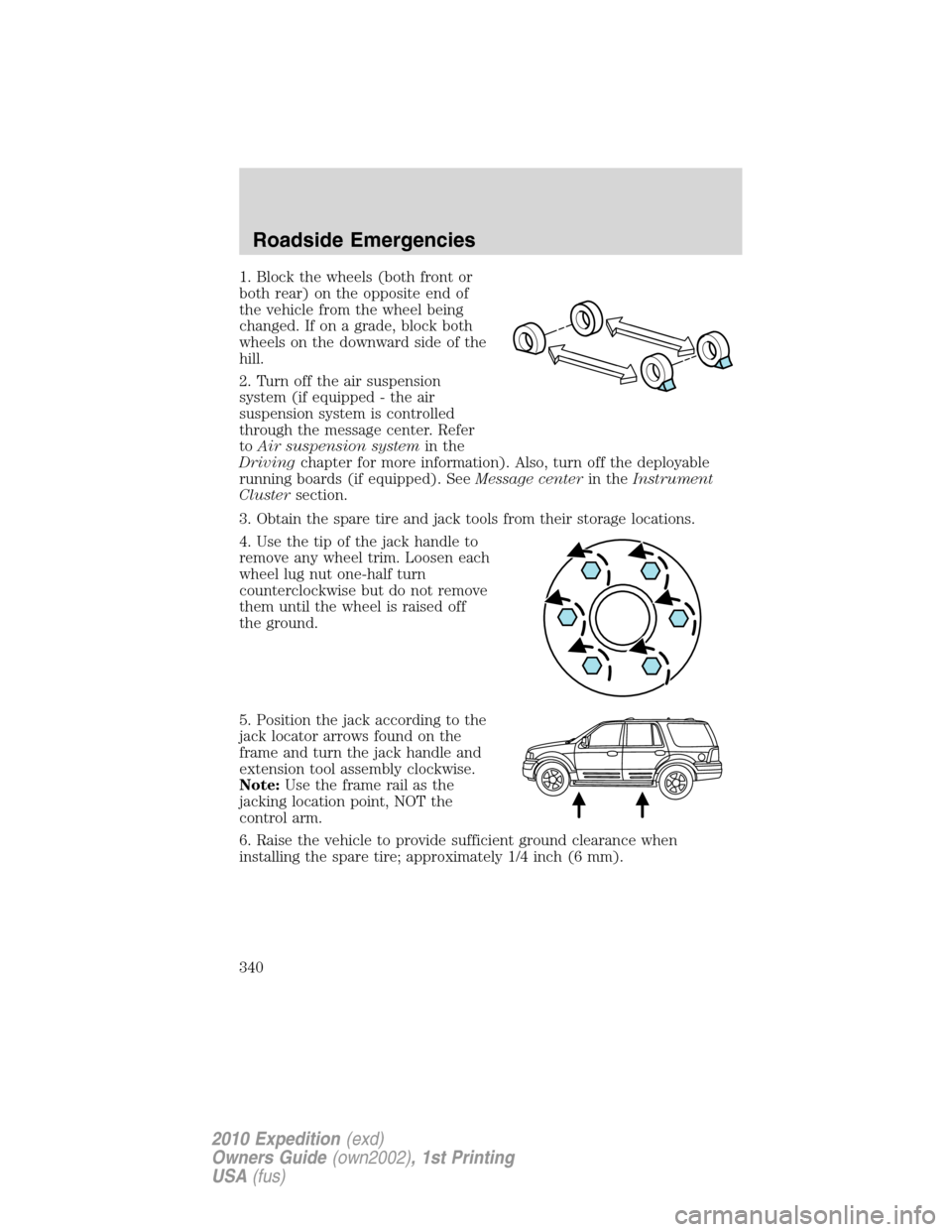
1. Block the wheels (both front or
both rear) on the opposite end of
the vehicle from the wheel being
changed. If on a grade, block both
wheels on the downward side of the
hill.
2. Turn off the air suspension
system (if equipped - the air
suspension system is controlled
through the message center. Refer
toAir suspension systemin the
Drivingchapter for more information). Also, turn off the deployable
running boards (if equipped). SeeMessage centerin theInstrument
Clustersection.
3. Obtain the spare tire and jack tools from their storage locations.
4. Use the tip of the jack handle to
remove any wheel trim. Loosen each
wheel lug nut one-half turn
counterclockwise but do not remove
them until the wheel is raised off
the ground.
5. Position the jack according to the
jack locator arrows found on the
frame and turn the jack handle and
extension tool assembly clockwise.
Note:Use the frame rail as the
jacking location point, NOT the
control arm.
6. Raise the vehicle to provide sufficient ground clearance when
installing the spare tire; approximately 1/4 inch (6 mm).
Roadside Emergencies
340
2010 Expedition(exd)
Owners Guide(own2002), 1st Printing
USA(fus)
Page 342 of 420
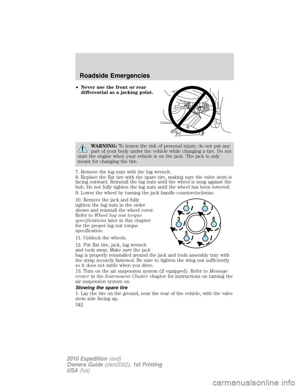
•Never use the front or rear
differential as a jacking point.
WARNING:To lessen the risk of personal injury, do not put any
part of your body under the vehicle while changing a tire. Do not
start the engine when your vehicle is on the jack. The jack is only
meant for changing the tire.
7. Remove the lug nuts with the lug wrench.
8. Replace the flat tire with the spare tire, making sure the valve stem is
facing outward. Reinstall the lug nuts until the wheel is snug against the
hub. Do not fully tighten the lug nuts until the wheel has been lowered.
9. Lower the wheel by turning the jack handle counterclockwise.
10. Remove the jack and fully
tighten the lug nuts in the order
shown and reinstall the wheel cover.
Refer toWheel lug nut torque
specificationslater in this chapter
for the proper lug nut torque
specification.
11. Unblock the wheels.
12. Put flat tire, jack, lug wrench
and tools away. Make sure the jack
bag is properly reinstalled around the jack and tools assembly tray with
the strap securely fastened. Be sure to tighten the wing nut sufficiently
so it does not rattle when you drive.
13. Turn on the air suspension system (if equipped). Refer toMessage
centerin theInstrument Clusterchapter for instructions on turning the
air suspension system on.
Stowing the spare tire
1. Lay the tire on the ground, near the rear of the vehicle, with the valve
stem side facing up.
Roadside Emergencies
342
2010 Expedition(exd)
Owners Guide(own2002), 1st Printing
USA(fus)
Page 343 of 420
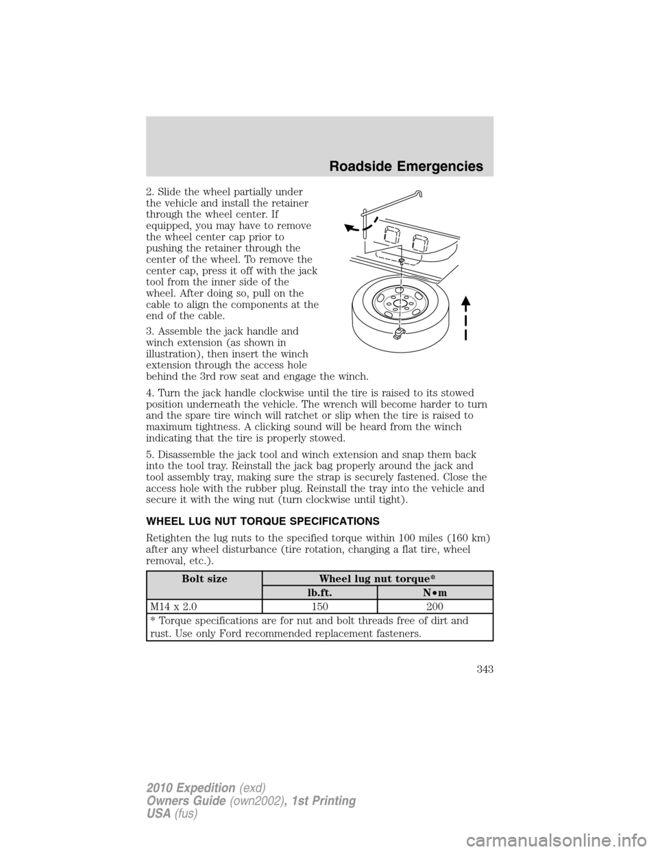
2. Slide the wheel partially under
the vehicle and install the retainer
through the wheel center. If
equipped, you may have to remove
the wheel center cap prior to
pushing the retainer through the
center of the wheel. To remove the
center cap, press it off with the jack
tool from the inner side of the
wheel. After doing so, pull on the
cable to align the components at the
end of the cable.
3. Assemble the jack handle and
winch extension (as shown in
illustration), then insert the winch
extension through the access hole
behind the 3rd row seat and engage the winch.
4. Turn the jack handle clockwise until the tire is raised to its stowed
position underneath the vehicle. The wrench will become harder to turn
and the spare tire winch will ratchet or slip when the tire is raised to
maximum tightness. A clicking sound will be heard from the winch
indicating that the tire is properly stowed.
5. Disassemble the jack tool and winch extension and snap them back
into the tool tray. Reinstall the jack bag properly around the jack and
tool assembly tray, making sure the strap is securely fastened. Close the
access hole with the rubber plug. Reinstall the tray into the vehicle and
secure it with the wing nut (turn clockwise until tight).
WHEEL LUG NUT TORQUE SPECIFICATIONS
Retighten the lug nuts to the specified torque within 100 miles (160 km)
after any wheel disturbance (tire rotation, changing a flat tire, wheel
removal, etc.).
Bolt size Wheel lug nut torque*
lb.ft. N•m
M14 x 2.0 150 200
* Torque specifications are for nut and bolt threads free of dirt and
rust. Use only Ford recommended replacement fasteners.
Roadside Emergencies
343
2010 Expedition(exd)
Owners Guide(own2002), 1st Printing
USA(fus)
Page 374 of 420
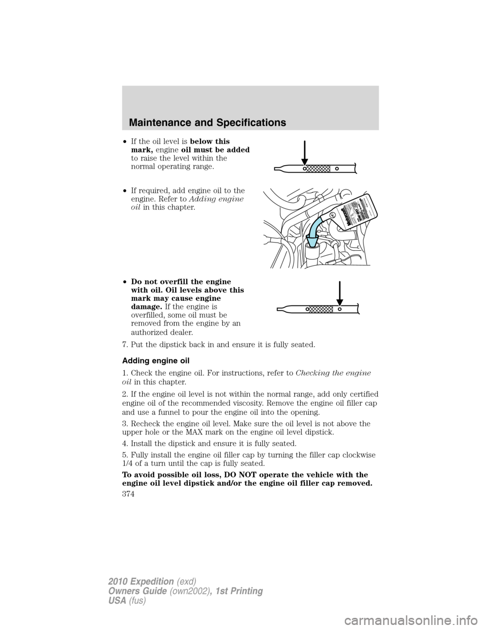
•If the oil level isbelow this
mark,engineoil must be added
to raise the level within the
normal operating range.
•If required, add engine oil to the
engine. Refer toAdding engine
oilin this chapter.
•Do not overfill the engine
with oil. Oil levels above this
mark may cause engine
damage.If the engine is
overfilled, some oil must be
removed from the engine by an
authorized dealer.
7. Put the dipstick back in and ensure it is fully seated.
Adding engine oil
1. Check the engine oil. For instructions, refer toChecking the engine
oilin this chapter.
2. If the engine oil level is not within the normal range, add only certified
engine oil of the recommended viscosity. Remove the engine oil filler cap
and use a funnel to pour the engine oil into the opening.
3. Recheck the engine oil level. Make sure the oil level is not above the
upper hole or the MAX mark on the engine oil level dipstick.
4. Install the dipstick and ensure it is fully seated.
5. Fully install the engine oil filler cap by turning the filler cap clockwise
1/4 of a turn until the cap is fully seated.
To avoid possible oil loss, DO NOT operate the vehicle with the
engine oil level dipstick and/or the engine oil filler cap removed.
Maintenance and Specifications
374
2010 Expedition(exd)
Owners Guide(own2002), 1st Printing
USA(fus)
Page 378 of 420
•If you do not allow the engine to relearn its idle trim, the idle
quality of your vehicle may be adversely affected until the idle
trim is eventually relearned.
If the battery has been disconnected or a new battery has been installed,
the clock and the preset radio stations must be reset once the battery is
reconnected.
•Always dispose of automotive
batteries in a responsible manner.
Follow your local authorized
standards for disposal. Call your
local authorized recycling center
to find out more about recycling
automotive batteries.
ENGINE COOLANT
Checking engine coolant
The concentration and level of engine coolant should be checked at the
intervals listed inscheduled maintenance information.The coolant
concentration should be maintained at 50/50 coolant and distilled water,
which equates to a freeze point of -34°F (-36°C). Coolant concentration
testing is possible with a hydrometer or antifreeze tester. The level of
coolant should be maintained at the FULL COLD level or within the
COLD FILL RANGE in the coolant reservoir. If the level falls below, add
coolant per the instructions in theAdding engine coolantsection.
Your vehicle was factory-filled with a 50/50 engine coolant and water
concentration. If the concentration of coolant falls below 40% or above
60%, the engine parts could become damaged or not work properly.A
50/50 mixture of coolant and water provides the following:
•Freeze protection down to -34°F (-36°C).
•Boiling protection up to 265°F (129°C).
•Protection against rust and other forms of corrosion.
•Proper function of calibrated gauges.
L
E
A
D
RETURN
RECYCLE
Maintenance and Specifications
378
2010 Expedition(exd)
Owners Guide(own2002), 1st Printing
USA(fus)