2010 DODGE VIPER light
[x] Cancel search: lightPage 23 of 80

To L o w e r T h e To p
• Lower both windows 1 in (2.5 cm).
• Lower both sun visors.
• Depress button at top of latch and pull thelatch handle downward and rearward.
• Open the trunk.
• Pull the top all the way back into the storage well behind the seats.
• Lock convertible top into place by engaging the top latch.
• Close the trunk.
• Raise the sun visors to the desired position.
• Reverse procedure to raise the top.
• Refer to your Owner's Manual on the DVD for complete details.
WIND BUFFETING
• Wind buffeting can be described as a helicopter-type percussion sound. If buffeting occurs with the windows down, or top down (convertible models), adjust one or both
windows up or down slightly.
21
OPERATING YOUR VEHICLE
Page 26 of 80

NON-TOUCH-SCREEN RADIO
Navigation Radio – RB1
• The radio sales code is located on the upper left side of radio faceplate.
Radio Mode
• Press the AM/FM button to toggle between AM and FM modes.
Seek Up/Down
• Press to seek through radio stations in AM or FM bands and to seek through tracks inCD mode.
Tune Up/Down
• In AM or FM modes, press to increase or decrease the radio frequency. In CD modepress to fast forward or fast rewind a track.
Clock Setting
• To manually set the clock, use a ballpoint pen or similar object. When pressing eitherthe hour (H) or minute (M) button the Setup screen appears.
• To adjust the hours, press the “H” (hour) button.
• To adjust the minutes, press the “M” (minute) button.
• Turn the Selector knob to highlight DONE and press ENTER or wait 5 seconds.
ELECTRONICS
24
Page 27 of 80

Daylight Savings
• Use a ball point pen or similar object to press the "H" (hour) or "M" (Minute) button toaccess the clock setup screen.
• Press ENTER to select Clock Setup.
• Rotate the Selector knob to highlight Daylight Savings and press ENTER.
• Rotate the Selector knob to highlight St andard or Daylight Savings and press ENTER.
• Turn the Selector knob to highlight DONE and press ENTER or wait 5 seconds.
Changing Time Zone
• Use a ball point pen or similar object to press the "H" (hour) or "M" (Minute) button to access the clock setup screen.
• Press ENTER to select Clock Setup.
• Rotate the Selector knob to highlight Time Zone and press ENTER.
• Rotate the Selector knob to highlight the desired Time Zone and press ENTER.
• Turn the Selector knob to highlight DONE and press ENTER or wait 5 seconds.
Store Radio Presets
• Find the station to store by either pressing the seek up/down button, the tune up/down button, or by t ouching the SCAN button.
• Turn the Selector knob to highlight SET and press ENTER. SET 1 appears on the display.
• Then select button (1–5).
• You may add a second station to each pushb utton by repeating the above procedure
with this exception: After highlighting SET, press ENTER twice. SET 2 appears on the
display, then select button (1–5).
Navigation
Navigation Radio – RB1 Only
• Your navigation system receives GPS signals from up to 8 satellites to display the position and direction of your vehicle.
• Map and database information is supplied through a DVD-ROM and vehicle sensors enable the system to display the present vehicle position even in locations where GPS
may be blocked.
• The DVD-ROM disc must be inserted into the radio before accessing the Navigation mode.
NOTE: Many features of this radio are speed dependent. For your own safety, some of
the programmable options will be grayed out and unavailable while the vehicle is in
motion. Pull over at a safe location to complete your task.
New Destination
• Press the NAV button to access the NAV Main Menu.
• Using the Selector knob, highlight Destination to program a destination, press ENTER, then select one of the 8 ways to input a destination.
25
ELECTRONICS
Page 28 of 80

Program Destination by Street Address
• Press the NAV button to access the NAV Main Menu.
• Select/highlight Destination from the Main Menu screen and press ENTER.
• Select/highlight Street Address from the Find Destination by screen and press ENTER.
• Select/highlight Street Name from the Find Address screen and press ENTER.
NOTE: City, State and Province can be also be changed in the Find Address screen.
• The Input Street Name screen appears. Use the Selector knob to spell out the street
name. Select/highlight each letter and press ENTER.
• Select/highlight Street List and press ENTER to continue. The Select Street Name screen appears. Select/highlight the c orrect street and press ENTER.
• The Input Address screen appears. Us e the Selector knob to input the address
number. When finished, select/highlight Done and press ENTER.
• Lastly, the Confirm Destination screen appe ars, showing the address of the selected
destination. If it is correct, select/highlight OK and press ENTER. The system will
calculate a route to that destination.
Address Book
• Press the NAV button, use the Selector knob to highlight Destination and press ENTER.
• Select/highlight one of the eight choices to input a destination and press ENTER.
• Enter the address information following the screen prompts.
• Once a destination has been entered, select/highlight Options from the Confirm Destination screen and press ENTER.
• Select/Highlight Save in Address Book and press ENTER.
• The Input Name screen appears. Use the Select Encoder to spell out the name you
would like to see in the Address Book.
• Select/highlight Done when finished and press ENTER.
• The Input Phone Number screen appears. Use the Select Encoder to input the phone
number of the address. When the number is complete, or if you do not know the
phone number, select/highlight Save and press ENTER.
• The name, address and phone number are now stored in the address book. The Confirm Destination screen will reappear showing the saved information.
Map
• Press the NAV button and select/highlight Map and press ENTER.
• The Map screen will appear showing your current location.
Adjusting Navigation Volume
• The navigation volume can be adjusted during a voice command by using the radioPower/Volume control knob.
• To repeat a voice command select the voice icon on the Map or Arrow guidance.
ELECTRONICS
26
Page 32 of 80

Front Splitter
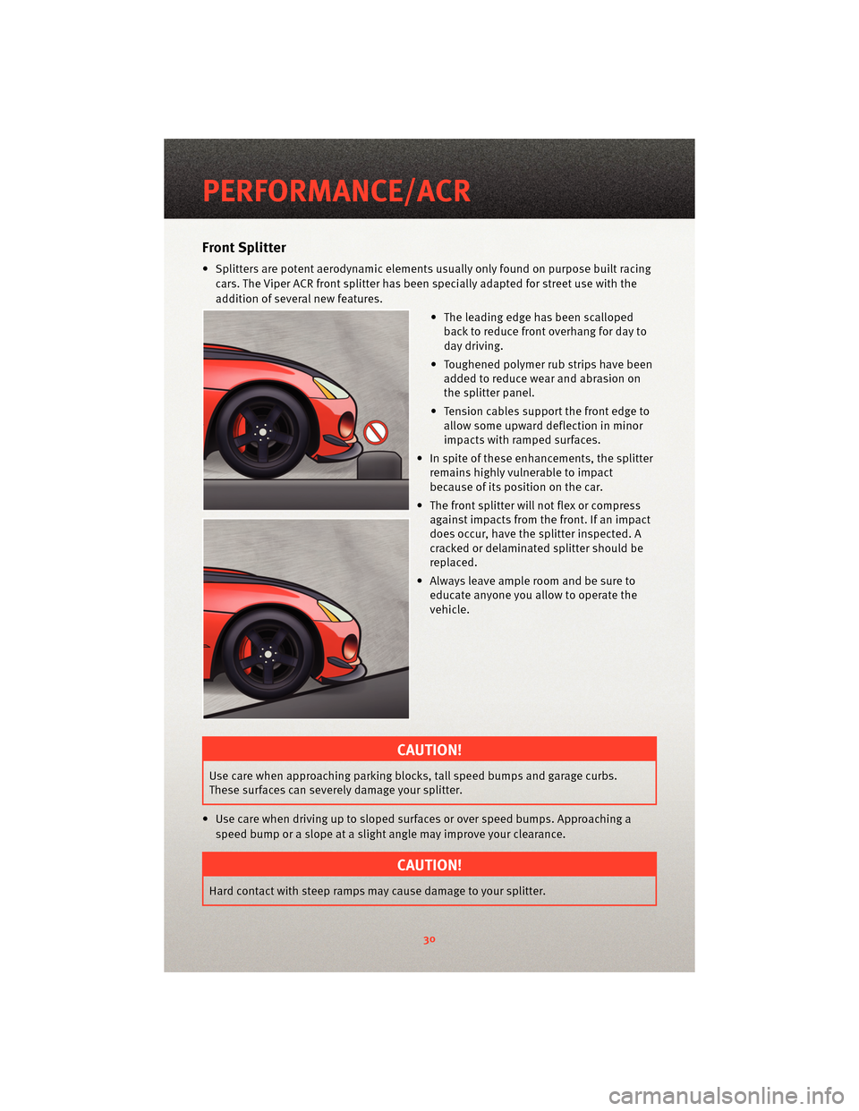
• Splitters are potent aerodynamic elements usually only found on purpose built racing
cars. The Viper ACR front splitter has been specially adapted for street use with the
addition of several new features.
• The leading edge has been scallopedback to reduce front overhang for day to
day driving.
• Toughened polymer rub strips have been added to reduce wea r and abrasion on
the splitter panel.
• Tension cables support the front edge to allow some upward deflection in minor
impacts with ramped surfaces.
• In spite of these enhancements, the splitter remains highly vulnerable to impact
because of its position on the car.
• The front splitter will not flex or compress against impacts from the front. If an impact
does occur, have the splitter inspected. A
cracked or delaminated splitter should be
replaced.
• Always leave ample room and be sure to educate anyone you allow to operate the
vehicle.
CAUTION!
Use care when approaching parking bloc ks, tall speed bumps and garage curbs.
These surfaces can severely damage your splitter.
• Use care when driving up to sloped surfaces or over speed bumps. Approaching a speed bump or a slope at a slight angle may improve your clearance.
CAUTION!
Hard contact with steep ramps may cause damage to your splitter.
PERFORMANCE/ACR
30
Page 36 of 80

• The rear wing on the non two-tone ACR is molded completely with unidirectionalcarbon fiber and painted in body color. Some patterned or linear conditions may be
visible in the p ainted carbon fiber surfaces. This i s also a normal result of the carbon
fiber process.
TWO PIECE BRAKE ROTORS
• The Viper SRT10 is known for having world class brakes . The Viper ACR takes this
incredible braking system to the next level
with the Stop Tech two-piece lightweight
slotted rotors. These brake rotors
significantly reduce rotating un-sprung
mass. They also improve brake cooling and
reduce on-track fade.
CAUTION!
The slotted rotors may increase brake pad wear depending on driving conditions.
These rotors may also produce some additional brake noise due to the high
performance two-piece construction.
• It is normal for the brakes to make some popping or creaking noises as they cool down. This is the result of the two-piece construction.
• Although the brake rotors are a two-piece construction, they should be replaced as a complete assembly.
CAUTION!
During brake pad replacement the pads must be loaded so that the wear sensor is on
the inboard side of the caliper and the trailing side of the wheel rotation (all four
wheels).
Street Break-in Procedure
• Try to avoid abrupt, hard stops for the first 200 miles (300 km).
• Avoid any racing OR off-road activities for the first 200 miles (300 km).
• Avoid repeated incline/decline braking for the first 200 miles (300 km).
PERFORMANCE/ACR
34
Page 37 of 80

Alternate Break in Procedure
CAUTION!
Chrysler does not endorse speeding on public roads; therefore, if a safe area cannot
be used for break-in, you must perform the street break-in procedure. Regardless of
completing the “street brea k-in procedure,” this alternative break-in procedure is
recommended before any track use of the vehicle.
• In the event that the street break-in procedure can’t be performed before the pads and
rotors are thermally stressed, use the following procedure:
• Read through the procedure and find a suitab le, safe and legal area to perform the
necessary stops.
• BEFORE starting the break-in procedure, drive with gentle braking. Do not use
brakes aggressively until performing brake-in procedure.
• Make a series of 10 stops from 60 to 5-10 MPH. At the end of each stop, immediately accelerate to 60 again for the next stop. Run all stops continuously in
one cycle.
NOTE: A moderate braking effort is needed to properly break in the rotors and pads. A
stopping force of approxim ately 0.8G’s, just short of ABS intervention, is the level of
pedal effort you are trying to attain.
• During the 60 to 5-10 MPH series of stops, the exact speed is not critical. Accelerateto approximately 60 and begin the brak ing cycle. As you approach 5-10 MPH, it is
not necessary to watch the speedometer. Keep your eyes on the road and
approximate your speed at the end of each cycle.
CAUTION!
Do not come to a complete stop! This will imprint pad material onto the rotor, causing
a vibration during future use.
• Watch for the following:
• On the 8th or 9th stop, there should be a distinct smell from the brakes. Smoke may be evident during earlier stops as well.
• Also on the 8th or 9th stop, some friction materials will experience “green fade”. This is a slight fading of the brakes. The fade will
stabilize, but not completely go away until the brakes have cooled.
• After the break-in cycle is finished there will be a light gray film on the rotor face. The gray film is pad material starting to transfer onto the
rotor face.
35
PERFORMANCE/ACR
Page 45 of 80

HARD CORE PACKAGE
• This option is for the Hard Core track enthusiast who is looking for maximum weight
savings.
• The Hard Core Package eliminates the Audio System (including the radio, amplifier,
door speakers and subwoofer). Also delet ed are the under hood silencer pad, the
trunk carpet and the tire inflator. The door speakers are replaced by carbon fiber
panels. The radio is replaced by a lightweight cover that can be configured to mount
the included Lap Timer.
CAUTION!
The tire inflator has been removed from the Hard Core package. There are no
measures for flat tire repair included with this vehicle. It is recommended that drivers
always bring a mobile phone in case of a flat tire.
• The removal of the trunk carpeting reduces sound insulation. It is normal to hear more road and drivetrain noise.
• The Lap Timer kit includes the Timer, Beacon Receiver, a power cord, download kit and the Beacon Transmitter.
• The Lap Timer displays lap times on a large illuminated digital display. It continuously updates the fastest laps and acquires a running data log of all times during the track
event. This data can be do wnloaded for analysis via a USB connection. Refer to your
AiM lap timer manual for instructions.
• The cables to the beacon receiver and power jack include extra long lengths. This is to provide the ability to custom fit the timer and beacon receiver depending on the track
and/or driver preference.
• Note on Lap Timer: For lap timer software updates and technical support contact www.aimsports.com/software/index.html.
43
PERFORMANCE/ACR