Page 90 of 315

WARNING!
•Adjusting a seat while the vehicle is moving is
dangerous. The sudden movement of the seat
could cause you to lose control. The seat belt might
not be properly adjusted and you could be injured.
Adjust the seat only while the vehicle is parked.
•Do not ride with the seatback reclined so that the
shoulder belt is no longer resting against your
chest. In an accident, you could slide under the
seat belt and be seriously or even fatally injured.
Use the recliner only when the vehicle is parked.
Recliner Adjustment
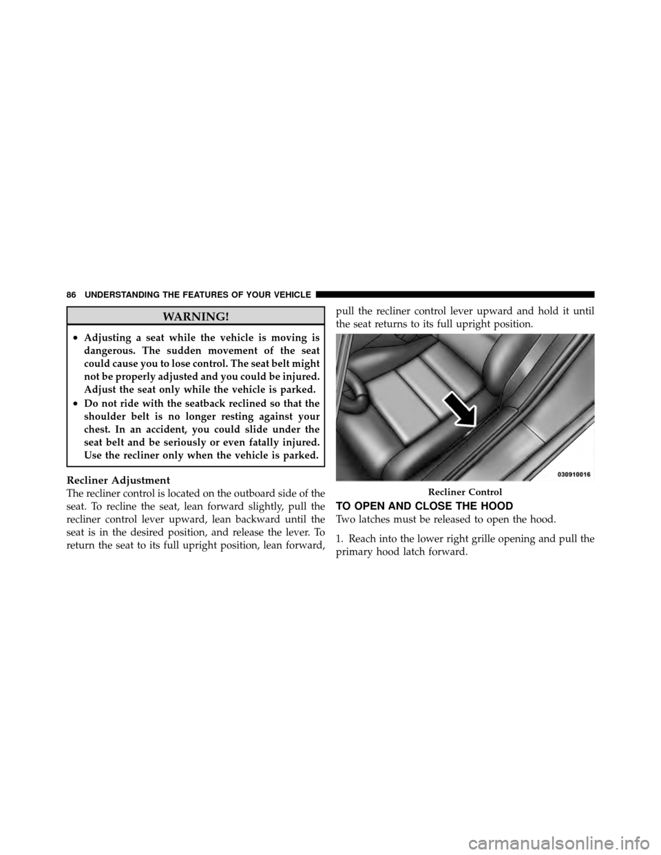
The recliner control is located on the outboard side of the
seat. To recline the seat, lean forward slightly, pull the
recliner control lever upward, lean backward until the
seat is in the desired position, and release the lever. To
return the seat to its full upright position, lean forward,pull the recliner control lever upward and hold it until
the seat returns to its full upright position.
TO OPEN AND CLOSE THE HOOD
Two latches must be released to open the hood.
1. Reach into the lower right grille opening and pull the
primary hood latch forward.
Recliner Control
86 UNDERSTANDING THE FEATURES OF YOUR VEHICLE
Page 92 of 315

CAUTION!
•Do not leave the hood open in areas where strong
gusts of wind are likely. Such a place might be by
the side of the road where large trucks pass by.
Strong gusts of wind may damage your hood.
Always close the hood in such situations.
•To prevent possible damage, do not slam the hood
to close it. Simply lower the hood until it is open
approximately 6 in (15 cm) and then drop it. This
should secure both latches. Never drive your ve-
hicle unless the hood is fully closed with both
latches engaged.
WARNING!
Be sure the hood is fully latched before driving your
vehicle. If the hood is not fully latched, it could open
when the vehicle is in motion and block your vision.
Failure to follow this warning could result in serious
injury or death.
LIGHTS
Exterior and Interior Lighting Control
The multifunction lever on the left side of the
steering column controls the operation of the
headlights, parking lights, turn signal lights, front
fog lights, instrument panel lights and interior lights.
Headlights and Parking Lights
Turn the end of the multifunction lever to the first detent
for parking light operation. Turn the end of the lever to
the second detent for headlight operation.
88 UNDERSTANDING THE FEATURES OF YOUR VEHICLE
Page 100 of 315

WARNING!
Sudden loss of visibility through the windshield
could lead to an accident. You might not see other
vehicles or other obstacles. To avoid sudden icing of
the windshield during freezing weather, warm the
windshield with defroster before and during wind-
shield washer use.
Mist Feature
From the off position, push the windshield wiper/
washer control lever downward to activate a single wipe
cycle to clear the windshield of road mist or spray from
a passing vehicle. The wipers will continue to operate
until you release the lever.
Windshield Washers
To use the washer, pull the windshield wiper/washer
control lever toward you and hold it for as long as
washer spray is desired.If you activate the washer while the windshield wiper is
in the delay range, the wipers will operate in low-speed
for two wipe cycles after releasing the lever and then
resume the intermittent interval previously selected.
If you activate the washer while the windshield wiper is
turned off, the wipers will operate for two wipe cycles
and then turn off.
TILT STEERING COLUMN
The tilt release lever is located below the multifunction
lever on the left side of the steering column. To tilt the
column, simply pull the release lever downward and
then move the steering wheel upward or downward as
desired. When the column is in the desired position, push
the release lever upward to lock the column firmly in
place.
96 UNDERSTANDING THE FEATURES OF YOUR VEHICLE
Page 101 of 315
WARNING!
Do not adjust the steering column while driving.
Adjusting the steering column while driving or driv-
ing with the steering column unlocked, could cause
the driver to lose control of the vehicle. Be sure the
steering column is locked before driving your ve-
hicle. Failure to follow this warning may result in
serious injury or death.
ADJUSTABLE PEDALS
The adjustable pedals system is designed to allow a
greater range of driver comfort for steering wheel tilt and
seat position. This feature allows the brake, accelerator,
and clutch pedals (if equipped) to move toward or away
from the driver to provide improved position with the
steering wheel.Tilt Steering Column Lever
3
UNDERSTANDING THE FEATURES OF YOUR VEHICLE 97
Page 103 of 315
WARNING!
Do not adjust the pedals while the vehicle is moving.
You could lose control and have an accident. Always
adjust the pedals while the vehicle is parked.
Adjustable Foot Rest
This feature allows the driver to adjust the foot rest
forward or backward and to rotate it upward or down-
ward to allow for greater driving comfort.
Adjustable Foot Rest
3
UNDERSTANDING THE FEATURES OF YOUR VEHICLE 99
Page 105 of 315
An additional power outlet is located inside the center
console. Open the lid of the console to access this outlet.
NOTE:Do not exceed the maximum power of 160 Watts
(13 Amps) at 12 Volts. If the 160 Watt (13 Amp) power
rating is exceeded the fuse protecting the system will
need to be replaced.WARNING!
To avoid serious injury or death:
•Only devices designed for use in this type of
outlet should be inserted into any 12 Volt outlet.
•Do not touch with wet hands.
•Close the lid when not in use and while driving
the vehicle.
•If this outlet is mishandled, it may cause an
electric shock and failure.
Center Console Power Outlet
3
UNDERSTANDING THE FEATURES OF YOUR VEHICLE 101
Page 113 of 315

Liquid Crystal Display (LCD) Panel
The LCD panel at the bottom of the speedometer displays
specific messages for given conditions. These messages
are as follows:
•The words “DOOR AJAR” will display if a door is not
closed completely. In addition, a single chime will
sound if you move the vehicle when a door is not
closed completely.
•The words “DOOR UNLOCKED” will flash in the
display if one door is unlocked and will remain on
steady if both doors are unlocked.
•The word “DECK” will flash in the display if the
trunk/liftgate is open.
•The words “LOW TIRE” will flash slowly in the
display and a chime will sound if the tire pressure is
low.
•The words “FLAT TIRE” will flash rapidly in the
display and a chime will sound if critically low tire
pressure is detected.
Message Center
When the appropriate conditions ex-
ist, the Message Center displays the
following indicators and warnings:
High Beam Light
This light will turn on when the high beam
headlights are on. Pull the Multifunction Lever on
the left side of the steering column toward you to switch
the headlights from low beam to high beam. Pull the
lever a second time to switch the headlights back to low
beam.
4
UNDERSTANDING YOUR INSTRUMENT PANEL 109
Page 114 of 315

Front Fog Light Indicator
This indicator will illuminate when the front fog
lights are on.
Anti-Lock Brake (ABS) Warning Light
The amber Anti-Lock Brake Warning Light will
turn on and stay on briefly as a bulb check
when the ignition is first turned on. If the light
does not turn on during starting, see your
authorized dealer for service.
This light also illuminates at vehicle start-up to indicate
that the ABS self-check is in process. If the light remains
on after start-up, or turns on and remains on at road
speeds, it may indicate a system malfunction or that the
system is inoperative. In this case, the system reverts to
standard non-anti-lock brakes. If this occurs, safely bring
the vehicle to a complete stop as soon as possible and
cycle the ignition key to attempt to reset the ABS. If the
light remains on, see your authorized dealer immediately to have the system serviced. Furthermore, if the red
BRAKE Warning Light and the amber ABS Warning
Light are on, and the parking brake is fully released, see
your authorized dealer immediately.WARNING!
If the ABS and/or Brake Warning Lights illuminate,
please seek service immediately! Your vehicle will
have diminished braking capability and control if
ABS and/or service brake systems are not working
properly. Have your brake system serviced immedi-
ately.
Malfunction Indicator Light (MIL)
The Malfunction Indicator Light (MIL) is part
of an onboard diagnostic system called OBD.
The OBD system monitors engine control sys-
tems. The light will turn on when the key is in
the ON/RUN position before engine start. If the light
110 UNDERSTANDING YOUR INSTRUMENT PANEL