Page 207 of 530
Storage Bin Safety Warning
Carefully follow these warnings to help prevent personal
injury or damage to your vehicle:
WARNING!
•Always close the storage bin covers when your
vehicle is unattended.
•Do not allow children to have access to the second
row seat storage bins. Once in the storage bin,
young children may not be able to escape. If
trapped in the storage bin, children can die from
suffocation or heat stroke.
•In an accident, serious injury could result if the
seat storage bin covers are not properly latched.(Continued)
WARNING! (Continued)
•Do not drive the vehicle with the storage bin
covers open. Keep the storage bin covers closed
and latched while the vehicle is in motion.
•Do not operate the storage bin covers while the
vehicle is in motion.
•Do not use a storage bin latch as a tie down.
CAUTION!
The storage bin cover must be flat and locked to
avoid damage from contact with the front seat tracks,
which have minimal clearance to the cover.
206 UNDERSTANDING THE FEATURES OF YOUR VEHICLE
Page 208 of 530
Seat Storage Bin Cover Emergency Release Lever
As a security measure, your vehicle may be built with a
Storage Bin Cover Emergency Release is built into the
storage bin cover latching mechanism.NOTE:
In the event of an individual being locked inside
the storage bin, the storage bin cover can be opened from
inside of the bin by pushing on the glow-in-the-dark
lever attached to the storage bin cover latching
mechanism.
Coat Hooks
Coat hooks are located along the headliner for the second
and third row seating positions. The coat hook load limit
is 10 lbs (4.5 kg). Exceeding the recommended load limit
can cause the coat hooks to break or disengage from the
vehicle.
Storage Bin Cover Emergency Release Lever
3
UNDERSTANDING THE FEATURES OF YOUR VEHICLE 207
Page 216 of 530
ROOF LUGGAGE RACK — IF EQUIPPED
The crossbars and side rails are designed to carry the
weight on vehicles equipped with a luggage rack. The
load must not exceed 150 lbs (68 kg), and should be
uniformly distributed over the luggage rack crossbars.
Distribute cargo weight evenly on the roof rack crossbars.
The roof rack does not increase the total load carrying
capacity of the vehicle. Be sure the total load of cargo
inside the vehicle plus that on the external rack does not
exceed the maximum vehicle load capacity.
To move the crossbars, loosen the thumb screws located
at the upper edge of each crossbar approximately six
turns, then move the crossbar to the desired position,
keeping the crossbars parallel to the rack frame. Once the
crossbar is in place, retighten the thumb screws to lock
the crossbar into position.Attempt to move the crossbar again to ensure that it has
properly locked into position.
NOTE:
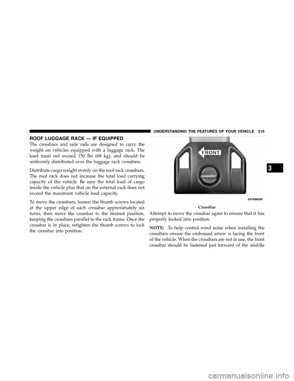
To help control wind noise when installing the
crossbars ensure the embossed arrow is facing the front
of the vehicle. When the crossbars are not in use, the front
crossbar should be fastened just forward of the middle
Crossbar
3
UNDERSTANDING THE FEATURES OF YOUR VEHICLE 215
Page 221 of 530
�Media Center 730N/430 (RER/REN/RBZ) —
AM/FM Stereo Radio And CD/DVD/HDD/
NAV — If Equipped .................... 257
▫ Operating Instructions — Voice Command
System (VR) — If Equipped ............. 258
▫ Operating Instructions — Uconnect™
Phone — If Equipped ................. 258
▫ Clock Setting Procedure — RBZ Radio ..... 258
▫ Clock Setting Procedure —
RER/REN Radio ..................... 260
� Media Center 130 (RES) — AM/FM Stereo
Radio With CD Player (MP3 AUX Jack) ....... 262
▫ Operating Instructions — Radio Mode ..... 263
▫ Operation Instructions — CD Mode For CD
And MP3 Audio Play ................. 266 ▫
Notes On Playing MP3 Files ............ 268
▫ Operation Instructions - Auxiliary Mode .... 270
� Media Center 130 (RES/RSC) — AM/FM
Stereo Radio With CD Player (MP3 AUX Jack)
And Sirius Radio ...................... 271
▫ Operating Instructions — Radio Mode ..... 271
▫ Operation Instructions — CD Mode For CD
And MP3 Audio Play ................. 277
▫ Notes On Playing MP3 Files ............ 279
▫ List Button (CD Mode For MP3 Play) ...... 281
▫ Info Button (CD Mode For MP3 Play) ...... 282
▫ Operating Instructions - Uconnect™ Phone
(If Equipped) ....................... 283
220 UNDERSTANDING YOUR INSTRUMENT PANEL
Page 229 of 530

WARNING!
A hot engine cooling system is dangerous. You or
others could be badly burned by steam or boiling
coolant. You may want to call an authorized dealer if
your vehicle overheats. If you decide to look under
the hood yourself, see “Maintaining Your Vehicle”.
Follow the warnings under the Cooling System Pres-
sure Cap paragraph.
4. Speedometer
Indicates vehicle speed.
5. Turn Signal Indicators The arrow will flash with the exterior turn signal
when the turn signal lever is operated.
If the vehicle electronics sense that the vehicle has
traveled about 1 mile (1.6 km) with the turn signals on, a continuous chime will sound to alert you to turn the
signals off. If either indicator flashes at a rapid rate, check
for a defective outside light bulb.
6. High Beam Indicator
This indicator shows that the high beam head-
lights are on. Push the multifunction lever forward
to switch the headlights to high beam and pull toward
yourself (normal position) to return to low beam.
7. Anti-Lock Brake (ABS) Light This light monitors the Anti-Lock Brake System
(ABS). The light will turn on when the ignition
switch is turned to the ON position and may
stay on for as long as four seconds.
If the ABS light remains on or turns on while driving, it
indicates that the Anti-Lock portion of the brake system
is not functioning and that service is required. However,
the conventional brake system will continue to operate
normally if the BRAKE warning light is not on.
228 UNDERSTANDING YOUR INSTRUMENT PANEL
Page 230 of 530
If the ABS light is on, the brake system should be serviced
as soon as possible to restore the benefits of Anti-Lock
brakes. If the ABS light does not turn on when the
Ignition switch is turned to the ON position, have the
light inspected by an authorized dealer.
8. Brake Warning LightThis light monitors various brake functions,
including brake fluid level and parking brake
application. If the brake light turns on, it may
indicate that the parking brake is applied, that
the brake fluid level is low, or that there is a problem with
the anti-lock brake system reservoir.
If the light remains on when the parking brake has been
disengaged, and the fluid level is at the full mark on the
master cylinder reservoir, it indicates a possible brake
hydraulic system malfunction or that a problem with the
Brake Booster has been detected by the Anti-Lock Brake
System (ABS) / Electronic Stability Program (ESP) sys-
tem. In this case, the light will remain on until the condition has been corrected. If the problem is related to
the brake booster, the ABS pump will run when applying
the brake and a brake pedal pulsation may be felt during
each stop.
The dual brake system provides a reserve braking capac-
ity in the event of a failure to a portion of the hydraulic
system. A leak in either half of the dual brake system is
indicated by the Brake Warning Light which will turn on
when the brake fluid level in the master cylinder has
dropped below a specified level.
The light will remain on until the cause is corrected.
NOTE:
The light may flash momentarily during sharp
cornering maneuvers which change fluid level condi-
tions. The vehicle should have service performed, and
the brake fluid level checked.
If brake failure is indicated, immediate repair is neces-
sary.
4
UNDERSTANDING YOUR INSTRUMENT PANEL 229
Page 231 of 530

WARNING!
Driving a vehicle with the red brake light on is
dangerous. Part of the brake system may have failed.
It will take longer to stop the vehicle. You could have
an accident. Have the vehicle checked immediately.
Vehicles equipped with the Anti-Lock Brake System
(ABS), are also equipped with Electronic Brake Force
Distribution (EBD). In the event of an EBD failure, the
Brake Warning Light will turn on along with the ABS
Light. Immediate repair to the ABS system is required.
Operation of the Brake Warning Light can be checked by
turning the ignition switch from the OFF position to the
ON position. The light should illuminate for approxi-
mately two seconds. The light should then turn off unless
the parking brake is applied or a brake fault is detected.
If the light does not illuminate, have the light inspected
by an authorized dealer. The light also will turn on when the parking brake is
applied with the ignition switch in the ON position.
NOTE:
This light shows only that the parking brake is
applied. It does not show the degree of brake application.
9. Tachometer — Premium Instrument Cluster Only
The white area of the scale shows the permissible engine
revolutions-per-minute (RPM x 1000) for each gear range.
Before reaching the red area, ease up on the accelerator to
prevent engine damage.
10. Shift Lever Indicator
The Shift Lever Indicator is self-contained within the
instrument cluster. It displays the gear position of the
automatic transmission.
NOTE: You must apply the brakes before shifting from
PARK.
230 UNDERSTANDING YOUR INSTRUMENT PANEL
Page 234 of 530
damaged, a “noFUSE” message will display in the odom-
eter display area. For further information on fuses and
fuse locations refer to “Fuses” in “Maintaining Your
Vehicle”.
CHAngE OIL
Your vehicle is equipped with an engine oil change
indicator system. The “Change Oil” message will flash in
the instrument cluster odometer for approximately
12 seconds after a single chime has sounded to indicate
the next scheduled oil change interval. The engine oil
change indicator system is duty cycle-based, which
means the engine oil change interval may fluctuate
dependent upon your personal driving style.
Unless reset, this message will continue to display each
time you turn the ignition switch to the ON/RUN
position. To turn off the message temporarily, press and
release the Trip Odometer button on the instrumentcluster. To reset the oil change indicator system (after
performing the scheduled maintenance), refer to the
following procedure:
1. Turn the ignition switch to the ON position (Do not
start the engine).
2. Fully depress the accelerator pedal slowly three times
within 10 seconds.
3. Turn the ignition switch to the OFF/LOCK position.
NOTE:
If the indicator message illuminates when you
start the vehicle, the oil change indicator system did not
reset. If necessary repeat this procedure.
13. Odometer / Trip Odometer Display Reset Button
To reset a message display (gATE, gASCAP, noFUSE,
CHAngE OIL, LoCOOL, LoWASH), push and hold the
button until the display resets (approximately two sec-
onds).
4
UNDERSTANDING YOUR INSTRUMENT PANEL 233