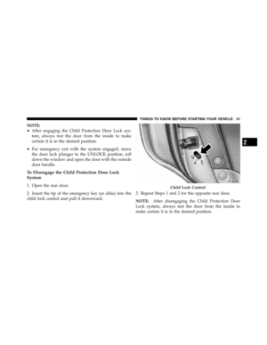
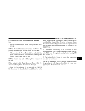
Page 169 of 432

19. Electronic Vehicle Information Center (EVIC)
Display
The odometer shows the total distance the vehicle has
been driven. The trip odometer shows individual trip
mileage. Refer to “Trip Odometer Button” for additional
information.
NOTE:U.S. Federal regulations require that upon trans-
fer of vehicle ownership, the seller certify to the pur-
chaser the correct mileage that the vehicle has been
driven. If your odometer needs to be repaired or serviced,
the repair technician should leave the odometer reading
the same as it was before the repair or service. If s/he
cannot do so, then the odometer must be set at zero, and
a sticker must be placed in the door jamb stating what the
mileage was before the repair or service. It is a good idea
for you to make a record of the odometer reading before
the repair/service, so that you can be sure that it is
properly reset, or that the door jamb sticker is accurate if
the odometer must be reset at zero. This display shows the Electronic Vehicle Information
Center (EVIC) messages when the appropriate conditions
exist. For further information refer to Electronic Vehicle
Information Center (EVIC).
Loose Fuel Filler Cap Message
If the vehicle diagnostic system determines that the fuel
filler cap is loose, improperly installed, or damaged, a
“Check Gascap” message will display in the odometer
display area. Tighten the fuel filler cap properly and
press the TRIP ODOMETER button to turn off the
message. If the problem continues, the message will
appear the next time the vehicle is started.
A loose, improperly installed, or damaged fuel filler cap
may also turn on the Malfunction Indicator Light (MIL).
168 UNDERSTANDING YOUR INSTRUMENT PANEL
Page 170 of 432

20. Brake Warning LightThis light monitors various brake functions,
including brake fluid level and parking brake
application. If the brake light turns on, it may
indicate that the parking brake is applied, that
the brake fluid level is low, or that there is a problem with
the anti-lock brake system reservoir.
If the light remains on when the parking brake has been
disengaged, and the fluid level is at the full mark on the
master cylinder reservoir, it indicates a possible brake
hydraulic system malfunction or that a problem with the
Brake Booster has been detected by the Anti-Lock Brake
System (ABS) / Electronic Stability Program (ESP) sys-
tem. In this case, the light will remain on until the
condition has been corrected. If the problem is related to
the brake booster, the ABS pump will run when applying
the brake and a brake pedal pulsation may be felt during
each stop. The dual brake system provides a reserve braking capac-
ity in the event of a failure to a portion of the hydraulic
system. A leak in either half of the dual brake system is
indicated by the Brake Warning Light which will turn on
when the brake fluid level in the master cylinder has
dropped below a specified level.
The light will remain on until the cause is corrected.
NOTE:
The light may flash momentarily during sharp
cornering maneuvers which change fluid level condi-
tions. The vehicle should have service performed, and
the brake fluid level checked.
If brake failure is indicated, immediate repair is neces-
sary.
4
UNDERSTANDING YOUR INSTRUMENT PANEL 169
Page 171 of 432

WARNING!
Driving a vehicle with the brake light on is danger-
ous. Part of the brake system may have failed. It will
take longer to stop the vehicle. You could have an
accident. Have the vehicle checked immediately.
Vehicles equipped with the Anti-Lock Brake System
(ABS), are also equipped with Electronic Brake Force
Distribution (EBD). In the event of an EBD failure, the
Brake Warning Light will turn on along with the ABS
Light. Immediate repair to the ABS system is required.
Operation of the Brake Warning Light can be checked by
turning the ignition switch from the OFF position to the
ON position. The light should illuminate for approxi-
mately two seconds. The light should then turn off unless
the parking brake is applied or a brake fault is detected.
If the light does not illuminate, have the light inspected
by an authorized dealer. The light also will turn on when the parking brake is
applied with the ignition switch in the ON position.
NOTE:
This light shows only that the parking brake is
applied. It does not show the degree of brake application.
21. Vehicle Security Light — If Equipped This light will flash at a fast rate for approxi-
mately 15 seconds, when the vehicle security
alarm is arming, and then will flash slowly
until the vehicle is disarmed.
22. Tire Pressure Monitoring Telltale Light Each tire, including the spare (if provided),
should be checked monthly, when cold and
inflated to the inflation pressure recommended
by the vehicle manufacturer on the vehicle
placard or tire inflation pressure label. (If your vehicle
has tires of a different size than the size indicated on the
170 UNDERSTANDING YOUR INSTRUMENT PANEL
Page 172 of 432

vehicle placard or tire inflation pressure label, you should
determine the proper tire inflation pressure for those
tires.)
As an added safety feature, your vehicle has been
equipped with a Tire Pressure Monitoring System
(TPMS) that illuminates a low tire pressure telltale when
one or more of your tires is significantly under-inflated.
Accordingly, when the low tire pressure telltale illumi-
nates, you should stop and check your tires as soon as
possible, and inflate them to the proper pressure. Driving
on a significantly under-inflated tire causes the tire to
overheat and can lead to tire failure. Under-inflation also
reduces fuel efficiency and tire tread life, and may affect
the vehicle’s handling and stopping ability.
Please note that the TPMS is not a substitute for proper
tire maintenance, and it is the driver ’s responsibility tomaintain correct tire pressure, even if under-inflation has
not reached the level to trigger illumination of the TPMS
low tire pressure telltale.
Your vehicle has also been equipped with a TPMS
malfunction indicator to indicate when the system is not
operating properly. The TPMS malfunction indicator is
combined with the low tire pressure telltale. When the
system detects a malfunction, the telltale will flash for
approximately one minute and then remain continuously
illuminated. This sequence will continue upon subse-
quent vehicle start-ups as long as the malfunction exists.
When the malfunction indicator is illuminated, the sys-
tem may not be able to detect or signal low tire pressure
as intended. TPMS malfunctions may occur for a variety
of reasons, including the installation of replacement or
alternate tires or wheels on the vehicle that prevent the
TPMS from functioning properly. Always check the
TPMS malfunction telltale after replacing one or more
4
UNDERSTANDING YOUR INSTRUMENT PANEL 171
Page 173 of 432

tires or wheels on your vehicle, to ensure that the
replacement or alternate tires and wheels allow the TPMS
to continue to function properly.
CAUTION!
The TPMS has been optimized for the original
equipment tires and wheels. TPMS pressures and
warning have been established for the tire size
equipped on your vehicle. Undesirable system opera-
tion or sensor damage may result when using re-
placement equipment that is not of the same size,
type, and/or style. Aftermarket wheels can cause
sensor damage. Do not use tire sealant from a can, or
balance beads if your vehicle is equipped with a
TPMS, as damage to the sensors may result.23. Anti-Lock Brake (ABS) Light
This light monitors the Anti-Lock Brake System
(ABS). The light will turn on when the ignition
switch is turned to the ON position and may stay on for
as long as four seconds.
If the ABS light remains on or turns on while driving,
then the Anti-Lock portion of the brake system is not
functioning and service is required. However, the con-
ventional brake system will continue to operate normally
if the BRAKE warning light is not on.
If the ABS light is on, the brake system should be serviced
as soon as possible to restore the benefits of Anti-Lock
Brakes. If the ABS light does not turn on when the
ignition switch is turned to the ON position, have the
light inspected by an authorized dealer.
24. Low Fuel Indicator Light This light will turn on and a single chime will
sound when the fuel level drops to 1/8 tank.
172 UNDERSTANDING YOUR INSTRUMENT PANEL
Page 174 of 432

25. Malfunction Indicator Light (MIL)The Malfunction Indicator Light (MIL) is part of
an onboard diagnostic system called OBD. The
OBD system monitors engine and automatic
transmission control systems. The MIL will turn on when
the key is in the ON position before engine start. If the
MIL does not come on when turning the key from LOCK
to ON, have the condition checked promptly.
Certain conditions such as a loose or missing gas cap,
poor fuel quality, etc., may illuminate the MIL after
engine start. The vehicle should be serviced if the MIL
stays on through several of your typical driving cycles. In
most situations, the vehicle will drive normally and will
not require towing.CAUTION!
Prolonged driving with the MIL on could cause
damage to the engine control system. It also could
affect fuel economy and drivability. If the MIL is
flashing, severe catalytic converter damage and
power loss will soon occur. Immediate service is
required.
WARNING!
A malfunctioning catalytic converter, as referenced
above, can reach higher temperatures than in normal
operating conditions. This can cause a fire if you
drive slowly or park over flammable substances such
as dry plants or wood or cardboard, etc. This could
result in death or serious injury to the driver, occu-
pants or others.
4
UNDERSTANDING YOUR INSTRUMENT PANEL 173
Page 175 of 432
ELECTRONIC VEHICLE INFORMATION CENTER
(EVIC)
The Electronic Vehicle Information Center (EVIC) fea-
tures a driver-interactive display that is located in the
instrument cluster.This system conveniently allows the driver to select a
variety of useful information by pressing the switches
mounted on the steering wheel. The EVIC consists of the
following:
•System status
•Vehicle information warning message displays
•Tire Pressure Monitor System
•Personal Settings (Customer-Programmable Features)
•Compass display
•Outside temperature display
•Trip computer functions,
•Uconnect™ Phone displays (if equipped)
•Uconnect™ gps screens (if equipped)
•Audio mode display
Electronic Vehicle Information Center
174 UNDERSTANDING YOUR INSTRUMENT PANEL
Page 176 of 432
![DODGE CHARGER SRT 2010 7.G Owners Manual •Surround Sound modes (if equipped with Driver-
Selectable Surround [DSS])
•Performance Pages (if equipped)
The system allows the driver to select information by
pressing the following buttons mou DODGE CHARGER SRT 2010 7.G Owners Manual •Surround Sound modes (if equipped with Driver-
Selectable Surround [DSS])
•Performance Pages (if equipped)
The system allows the driver to select information by
pressing the following buttons mou](/manual-img/12/5565/w960_5565-175.png)
•Surround Sound modes (if equipped with Driver-
Selectable Surround [DSS])
•Performance Pages (if equipped)
The system allows the driver to select information by
pressing the following buttons mounted on the steering
wheel. Press and release the MENU button and the
mode displayed will change between Trip
Functions, Performance Pages (if equipped),
Uconnect™ gps (if equipped), System Warn-
ings, System Status, and Personal Settings.
Press the FUNCTION SELECT button to
accept a selection. The FUNCTION SE-
LECT button also functions as a remote
sound system control. Refer to “Remote
Sound System Controls”. Press the SCROLL button to scroll through
Trip Functions, Performance Pages (if
equipped), Uconnect™ gps (if equipped),
System Status Messages, and Personal Set-
tings (Customer-Programmable Features).
The SCROLL button also functions as a
remote sound system control. Refer to “Remote Sound
System Controls”.
Press the AUDIO MODE button to select the
Compass/Temp/Audio screen. Along with
compass reading and outside temperature,
this screen will display radio and media
mode information depending on which ra-
dio is in the vehicle. Refer to “Remote Sound
System Controls”.
MENUButton
FUNCTION SELECTButton
SCROLL Button
AUDIOMODEButton
4
UNDERSTANDING YOUR INSTRUMENT PANEL 175