Page 200 of 538
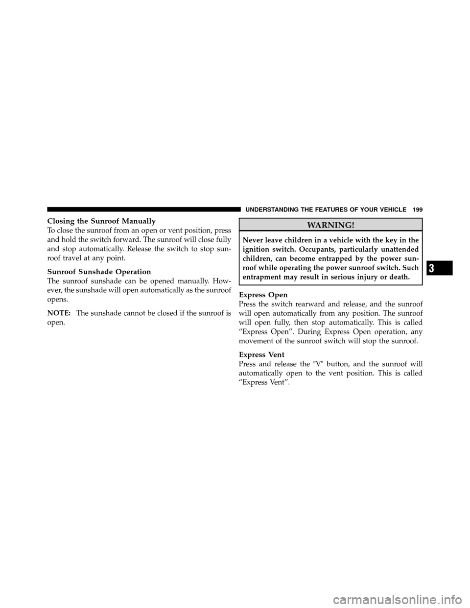
Closing the Sunroof Manually
To close the sunroof from an open or vent position, press
and hold the switch forward. The sunroof will close fully
and stop automatically. Release the switch to stop sun-
roof travel at any point.
Sunroof Sunshade Operation
The sunroof sunshade can be opened manually. How-
ever, the sunshade will open automatically as the sunroof
opens.
NOTE:The sunshade cannot be closed if the sunroof is
open.
WARNING!
Never leave children in a vehicle with the key in the
ignition switch. Occupants, particularly unattended
children, can become entrapped by the power sun-
roof while operating the power sunroof switch. Such
entrapment may result in serious injury or death.
Express Open
Press the switch rearward and release, and the sunroof
will open automatically from any position. The sunroof
will open fully, then stop automatically. This is called
“Express Open”. During Express Open operation, any
movement of the sunroof switch will stop the sunroof.
Express Vent
Press and release the �V�button, and the sunroof will
automatically open to the vent position. This is called
“Express Vent”.
3
UNDERSTANDING THE FEATURES OF YOUR VEHICLE 199
Page 201 of 538
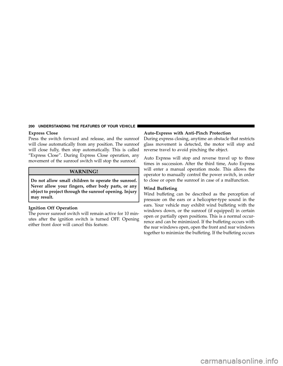
Express Close
Press the switch forward and release, and the sunroof
will close automatically from any position. The sunroof
will close fully, then stop automatically. This is called
“Express Close”. During Express Close operation, any
movement of the sunroof switch will stop the sunroof.
WARNING!
Do not allow small children to operate the sunroof.
Never allow your fingers, other body parts, or any
object to project through the sunroof opening. Injury
may result.
Ignition Off Operation
The power sunroof switch will remain active for 10 min-
utes after the ignition switch is turned OFF. Opening
either front door will cancel this feature.
Auto-Express with Anti-Pinch Protection
During express closing, anytime an obstacle that restricts
glass movement is detected, the motor will stop and
reverse travel to avoid pinching the object.
Auto Express will stop and reverse travel up to three
times in succession. After the third time, Auto Express
will enter a manual operation mode. This allows the
operator to manually control the power switch, in order
to close or open the sunroof in case of a malfunction.
Wind Buffeting
Wind buffeting can be described as the perception of
pressure on the ears or a helicopter-type sound in the
ears. Your vehicle may exhibit wind buffeting with the
windows down, or the sunroof (if equipped) in certain
open or partially open positions. This is a normal occur-
rence and can be minimized. If the buffeting occurs with
the rear windows open, open the front and rear windows
together to minimize the buffeting. If the buffeting occurs
200 UNDERSTANDING THE FEATURES OF YOUR VEHICLE
Page 202 of 538
with the sunroof open, adjust the sunroof opening to
minimize the buffeting or open any window.
Sunroof Maintenance
Use only a non-abrasive cleaner and a soft cloth to clean
the glass panel.
ELECTRICAL POWER OUTLETS — IF EQUIPPED
Two 12 Volt (13 Amp) power outlets are located on the
lower instrument panel, next to the open storage bin. The
upper power outlet is controlled by the ignition switch
and the lower power outlet is connected directly to the
battery. The upper power outlet will also operate a
conventional cigar lighter unit (if equipped with an
optional Smoker’s Package).
NOTE:
•To ensure proper operation a MOPAR�cigar knob and
element must be used.
•Do not exceed the maximum power of 160 Watts (13
Amps) at 12 Volts. If the 160 Watt (13 Amp) power
rating is exceeded the fuse protecting the system will
need to be replaced.
12 Volt Power Outlets
3
UNDERSTANDING THE FEATURES OF YOUR VEHICLE 201
Page 203 of 538
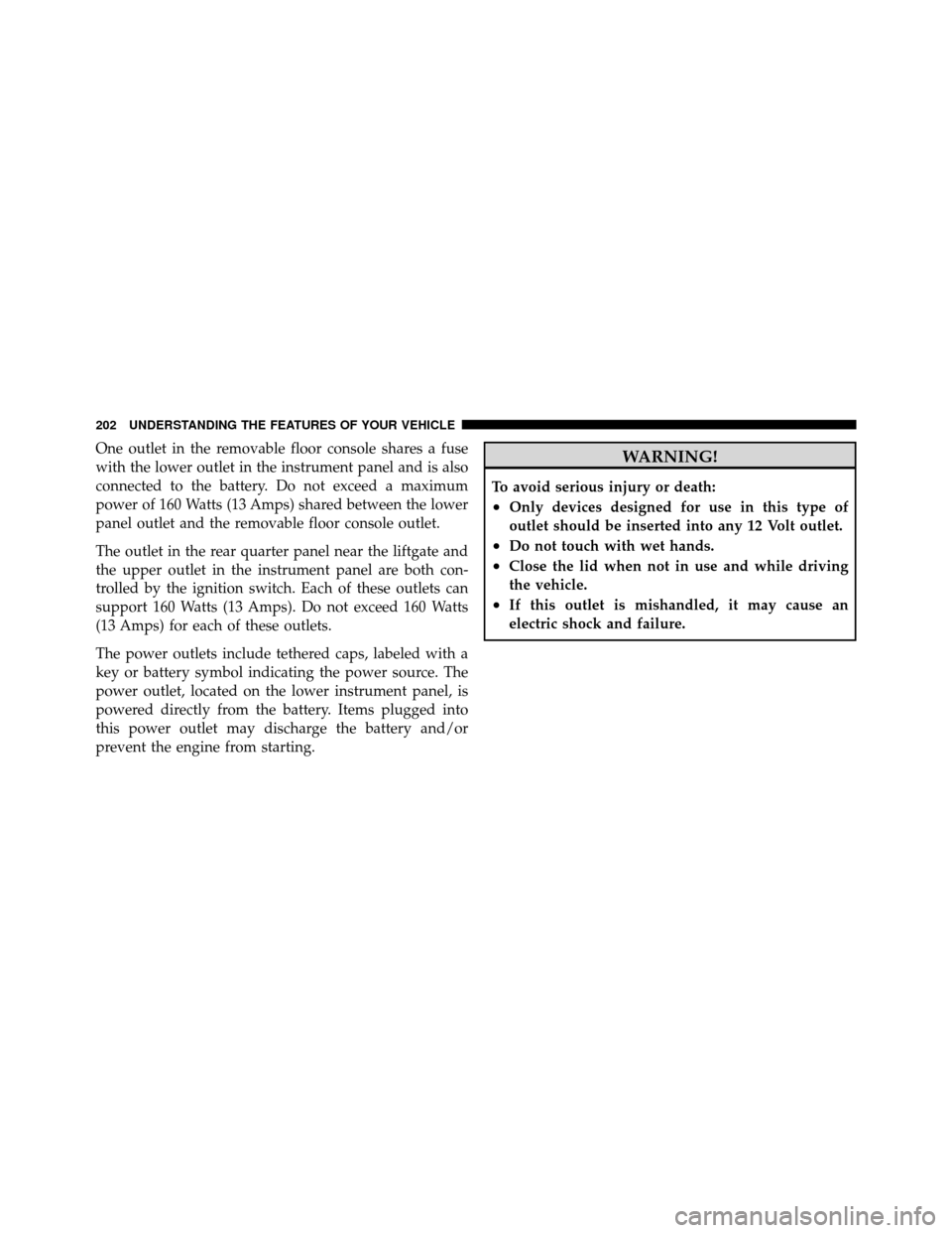
One outlet in the removable floor console shares a fuse
with the lower outlet in the instrument panel and is also
connected to the battery. Do not exceed a maximum
power of 160 Watts (13 Amps) shared between the lower
panel outlet and the removable floor console outlet.
The outlet in the rear quarter panel near the liftgate and
the upper outlet in the instrument panel are both con-
trolled by the ignition switch. Each of these outlets can
support 160 Watts (13 Amps). Do not exceed 160 Watts
(13 Amps) for each of these outlets.
The power outlets include tethered caps, labeled with a
key or battery symbol indicating the power source. The
power outlet, located on the lower instrument panel, is
powered directly from the battery. Items plugged into
this power outlet may discharge the battery and/or
prevent the engine from starting.WARNING!
To avoid serious injury or death:
•Only devices designed for use in this type of
outlet should be inserted into any 12 Volt outlet.
•Do not touch with wet hands.
•Close the lid when not in use and while driving
the vehicle.
•If this outlet is mishandled, it may cause an
electric shock and failure.
202 UNDERSTANDING THE FEATURES OF YOUR VEHICLE
Page 232 of 538
INSTRUMENT PANEL FEATURES
1 — Air Vents5 — Analog Clock 9 — DVD – If Equipped 13 — Switch Bank
2 — Instrument Cluster 6 — Upper Glove Compartment 10 — Cup Holders 14 — Ignition Switch
3 — Shift Lever 7 — Lower Glove Compart-
ment11 — Storage Bin
15 — Dimmer Switch
4 — Radio 8 — Climate Controls12 — Power Supply – 12V 16 — Headlight Switch
4
UNDERSTANDING YOUR INSTRUMENT PANEL 231
Page 234 of 538
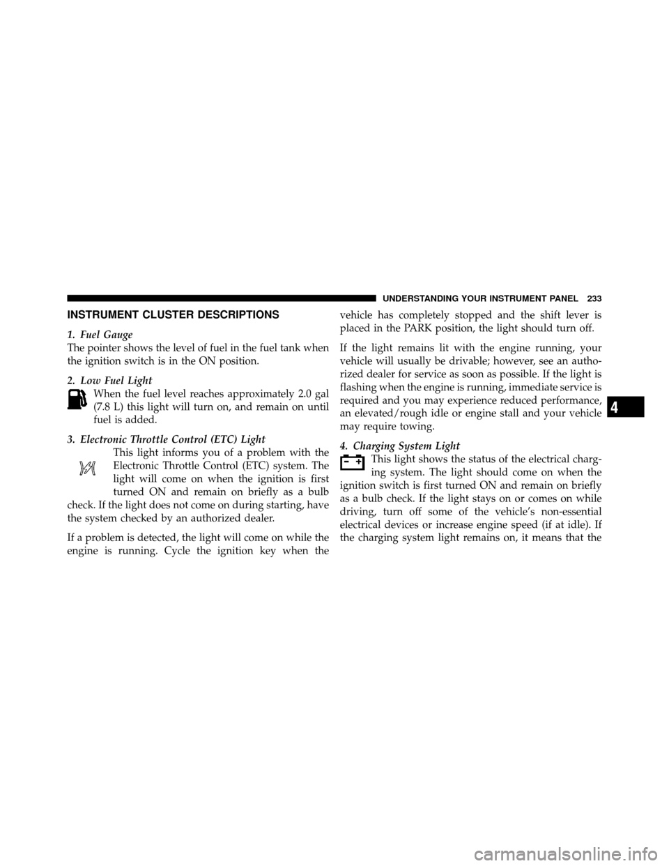
INSTRUMENT CLUSTER DESCRIPTIONS
1. Fuel Gauge
The pointer shows the level of fuel in the fuel tank when
the ignition switch is in the ON position.
2. Low Fuel LightWhen the fuel level reaches approximately 2.0 gal
(7.8 L) this light will turn on, and remain on until
fuel is added.
3. Electronic Throttle Control (ETC) Light This light informs you of a problem with the
Electronic Throttle Control (ETC) system. The
light will come on when the ignition is first
turned ON and remain on briefly as a bulb
check. If the light does not come on during starting, have
the system checked by an authorized dealer.
If a problem is detected, the light will come on while the
engine is running. Cycle the ignition key when the vehicle has completely stopped and the shift lever is
placed in the PARK position, the light should turn off.
If the light remains lit with the engine running, your
vehicle will usually be drivable; however, see an autho-
rized dealer for service as soon as possible. If the light is
flashing when the engine is running, immediate service is
required and you may experience reduced performance,
an elevated/rough idle or engine stall and your vehicle
may require towing.
4. Charging System Light
This light shows the status of the electrical charg-
ing system. The light should come on when the
ignition switch is first turned ON and remain on briefly
as a bulb check. If the light stays on or comes on while
driving, turn off some of the vehicle’s non-essential
electrical devices or increase engine speed (if at idle). If
the charging system light remains on, it means that the
4
UNDERSTANDING YOUR INSTRUMENT PANEL 233
Page 238 of 538
10. Electronic Stability Program (ESP) Indicator Light
/ Brake Assist System (BAS) Warning LightThe malfunction light for the Electronic Stabil-
ity Program (ESP) is combined with Brake
Assist System (BAS). The yellow “ESP/BAS
Warning Light” comes on when the ignition
switch is turned to the “ON” position. They should go
out with the engine running. If the “ESP/BAS Warning
Light” comes on continuously with the engine running, a
malfunction has been detected in either the ESP or the
BAS system. If this light remains on after several ignition
cycles, and the vehicle has been driven several miles
(kilometers) at speeds greater than 30 mph (48 km/h), see
an authorized dealer as soon as possible.WARNING!
If a warning light remains on the system may not be
working and you will not have the benefit of ESP or
BAS. Under certain driving conditions, where ESP or
BAS would be beneficial, you - if you have not
adjusted your driving speeds and stopping in or to
account for the lack of the feature, may be in acci-
dent.
11. Brake Warning Light This light monitors various brake functions,
including brake fluid level and parking brake
application. If the brake light turns on, it may
indicate that the parking brake is applied, that
the brake fluid level is low, or that there is a problem with
the anti-lock brake system reservoir.
4
UNDERSTANDING YOUR INSTRUMENT PANEL 237
Page 240 of 538
Operation of the Brake Warning Light can be checked by
turning the ignition switch from the OFF position to the
ON position. The light should illuminate for approxi-
mately two seconds. The light should then turn off unless
the parking brake is applied or a brake fault is detected.
If the light does not illuminate, have the light inspected
by an authorized dealer.
The light also will turn on when the parking brake is
applied with the ignition switch in the ON position.
NOTE:This light shows only that the parking brake is
applied. It does not show the degree of brake application.
12. Vehicle Security Light — If Equipped This light will flash at a fast rate for approxi-
mately 15 seconds, when the vehicle security
alarm is arming, and then will flash slowly
until the vehicle is disarmed. 13. Anti-Lock Brake (ABS) Light
This light monitors the Anti-Lock Brake System
(ABS). The light will turn on when the ignition
switch is turned to the ON position and may
stay on for as long as four seconds.
If the ABS light remains on or turns on while driving, it
indicates that the Anti-Lock portion of the brake system
is not functioning and that service is required. However,
the conventional brake system will continue to operate
normally if the BRAKE warning light is not on.
If the ABS light is on, the brake system should be serviced
as soon as possible to restore the benefits of Anti-Lock
brakes. If the ABS light does not turn on when the
Ignition switch is turned to the ON position, have the
light inspected by an authorized dealer.
4
UNDERSTANDING YOUR INSTRUMENT PANEL 239