Page 234 of 538
INSTRUMENT CLUSTER DESCRIPTIONS
1. Fuel Gauge
The pointer shows the level of fuel in the fuel tank when
the ignition switch is in the ON position.
2. Low Fuel LightWhen the fuel level reaches approximately 2.0 gal
(7.8 L) this light will turn on, and remain on until
fuel is added.
3. Electronic Throttle Control (ETC) Light This light informs you of a problem with the
Electronic Throttle Control (ETC) system. The
light will come on when the ignition is first
turned ON and remain on briefly as a bulb
check. If the light does not come on during starting, have
the system checked by an authorized dealer.
If a problem is detected, the light will come on while the
engine is running. Cycle the ignition key when the vehicle has completely stopped and the shift lever is
placed in the PARK position, the light should turn off.
If the light remains lit with the engine running, your
vehicle will usually be drivable; however, see an autho-
rized dealer for service as soon as possible. If the light is
flashing when the engine is running, immediate service is
required and you may experience reduced performance,
an elevated/rough idle or engine stall and your vehicle
may require towing.
4. Charging System Light
This light shows the status of the electrical charg-
ing system. The light should come on when the
ignition switch is first turned ON and remain on briefly
as a bulb check. If the light stays on or comes on while
driving, turn off some of the vehicle’s non-essential
electrical devices or increase engine speed (if at idle). If
the charging system light remains on, it means that the
4
UNDERSTANDING YOUR INSTRUMENT PANEL 233
Page 241 of 538
14. Electronic Stability Program (ESP) Indicator Light
/ Traction Control System (TCS) Indicator LightIf this indicator light flashes during accelera-
tion, apply as little throttle as possible. While
driving, ease up on the accelerator. Adapt your
speed and driving to the prevailing road con-
ditions, and do not switch off the Electronic Stability
Program (ESP), or Traction Control System (TCS).
15. Tachometer
The red segments indicate the maximum permissible
engine revolutions per minute (RPM x 1000) for each gear
range. Before reaching the red area, ease up on the
accelerator.
16. High Beam Indicator This indicator shows that the high beam head-
lights are on. Push the multifunction lever forward
to switch the headlights to high beam, and pull toward
yourself (normal position) to return to low beam. 17. Front Fog Light Indicator — If Equipped
This indicator will illuminate when the front fog
lights are on.
18. Seat Belt Reminder Light When the ignition switch is first turned ON, this
light will turn on for five to eight seconds as a bulb
check. During the bulb check, if the driver’s seat
belt is unbuckled, a chime will sound. After the bulb
check or when driving, if the driver’s seat belt remains
unbuckled, the Seat Belt Reminder Light will illuminate
and the chime will sound. Refer to “Occupant Restraints”
in “Things To Know Before Starting Your Vehicle” for
further information.
19. Malfunction Indicator Light (MIL) The Malfunction Indicator Light (MIL) is part of
an onboard diagnostic system, called OBD, that
monitors engine and automatic transmission con-
trol systems. The light will illuminate when the key is in
240 UNDERSTANDING YOUR INSTRUMENT PANEL
Page 242 of 538
the ON position, before engine start. If the bulb does not
come on when turning the key from OFF to ON, have the
condition checked promptly.
Certain conditions such as a loose or missing gas cap,
poor fuel quality, etc., may illuminate the MIL after
engine start. The vehicle should be serviced if the light
stays on through several of your typical driving cycles. In
most situations, the vehicle will drive normally and will
not require towing.
CAUTION!
Prolonged driving with the MIL on could cause
damage to the engine control system. It also could
affect fuel economy and drivability. If the MIL is
flashing, severe catalytic converter damage and
power loss will soon occur. Immediate service is
required.
WARNING!
A malfunctioning catalytic converter, as referenced
above, can reach higher temperatures than in normal
operating conditions. This can cause a fire if you
drive slowly or park over flammable substances such
as dry plants or wood or cardboard, etc. This could
result in death or serious injury to the driver, occu-
pants or others.
20. Airbag Warning Light This light will turn on for four to eight seconds
as a bulb check when the ignition switch is first
turned ON. If the light is either not on during
starting, stays on, or turns on while driving,
then have the system inspected at an authorized dealer as
soon as possible. Refer to “Occupant Restraints” in
“Things To Know Before Starting Your Vehicle” for
further information.
4
UNDERSTANDING YOUR INSTRUMENT PANEL 241
Page 243 of 538
21. Temperature Gauge
The temperature gauge shows engine coolant tempera-
ture. Any reading within the normal range indicates that
the engine cooling system is operating satisfactorily.
The gauge pointer will likely indicate a higher tempera-
ture when driving in hot weather, up mountain grades,
or when towing a trailer. It should not be allowed to
exceed the upper limits of the normal operating range.
CAUTION!
Driving with a hot engine cooling system could
damage your vehicle. If temperature gauge reads “H”
pull over and stop the vehicle. Idle the vehicle with
the air conditioner turned off until the pointer drops
back into the normal range. If the pointer remains on
the “H” and you hear continuous chimes, turn the
engine off immediately, and call an authorized deal-
ership for service.
WARNING!
A hot engine cooling system is dangerous. You or
others could be badly burned by steam or boiling
coolant. You may want to call an authorized dealer-
ship for service if your vehicle overheats. If you
decide to look under the hood yourself, see “Main-
taining Your Vehicle”. Follow the warnings under the
Cooling System Pressure Cap paragraph.
22. Odometer / Trip Odometer / ECO (Fuel Saver
Indicator) Button — If Equipped
Press this button to change the display from odometer to
either of two trip odometer settings or the ECO display.
The letter “A” or “B” will appear when in the trip
odometer mode. Push in and hold the button for two
seconds to reset the trip odometer to 0 miles (km). The
odometer must be in TRIP mode to reset it.
242 UNDERSTANDING YOUR INSTRUMENT PANEL
Page 306 of 538
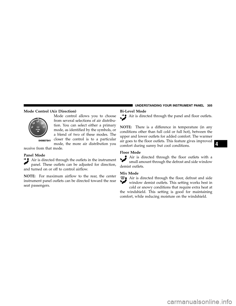
Mode Control (Air Direction)
Mode control allows you to choose
from several selections of air distribu-
tion. You can select either a primary
mode, as identified by the symbols, or
a blend of two of these modes. The
closer the control is to a particular
mode, the more air distribution you
receive from that mode.
Panel Mode
Air is directed through the outlets in the instrument
panel. These outlets can be adjusted for direction,
and turned on or off to control airflow.
NOTE: For maximum airflow to the rear, the center
instrument panel outlets can be directed toward the rear
seat passengers.
Bi-Level Mode
Air is directed through the panel and floor outlets.
NOTE: There is a difference in temperature (in any
conditions other than full cold or full hot), between the
upper and lower outlets for added comfort. The warmer
air goes to the floor outlets. This feature gives improved
comfort during sunny but cool conditions.
Floor Mode
Air is directed through the floor outlets with a
small amount through the defrost and side window
demist outlets.
Mix Mode
Air is directed through the floor, defrost and side
window demist outlets. This setting works best in
cold or snowy conditions that require extra heat at
the windshield. This setting is good for maintaining
comfort, while reducing moisture on the windshield.
4
UNDERSTANDING YOUR INSTRUMENT PANEL 305
Page 316 of 538
Manual Operation
This system offers a full complement of manual override
features. The AUTO symbol in the front ATC display will
be turned off when the system is being used in the
manual mode.
NOTE:Each of these features operate independently
from each other. If any one feature is controlled manually,
the temperature doors will continue to operate automati-
cally.
The blower fan speed can be set to any fixed speed by
pressing the Front Upper ATC Panel blower rocker
button. The fan will now operate at a fixed speed until
additional speeds are selected. This allows the front
occupants to control the volume of air circulated in the
vehicle and cancel the AUTO mode.
The operator can also select the direction of the airflow
by selecting one of the following positions. Panel Mode
Air is directed through the outlets in the instrument
panel. These outlets can be adjusted for direction,
and turned on or off to control airflow.
NOTE: For maximum airflow to the rear, the center
instrument panel outlets can be directed toward the rear
seat passengers.
Bi-Level Mode Air comes from the instrument panel outlets, floor
outlets and defrost outlets. A slight amount of air is
also directed through the side window demister outlets.
NOTE: In many temperature positions, the BI-LEVEL
mode is designed to provide cooler air out of the panel
outlets and warmer air from the floor outlets.
4
UNDERSTANDING YOUR INSTRUMENT PANEL 315
Page 327 of 538
▫Maintenance ........................ 387
� Adding Fuel ......................... 387
▫ Fuel Filler Cap (Gas Cap) .............. 387
▫ Loose Fuel Filler Cap Message ........... 389
� Vehicle Loading ...................... 389
▫ Vehicle Certification Label .............. 389�
Trailer Towing ........................ 394
▫ Common Towing Definitions ............ 394
▫ Towing Tips ........................ 407
� Recreational Towing
(Behind Motorhome, Etc.) ................ 409
326 STARTING AND OPERATING
Page 329 of 538
Extreme Cold Weather (Below�20°F or –29°C)
Follow the same instructions in the “Normal Starting”
procedure.
To ensure reliable starting at these temperatures, use of
an externally powered electric engine block heater (avail-
able from your authorized dealer) is recommended.
If The Engine Fails To Start
WARNING!
•Never pour fuel or other flammable liquids into
the throttle body air inlet opening in an attempt to
start the vehicle. This could result in a flash fire
causing serious personal injury.
(Continued)
WARNING! (Continued)
•Do not attempt to push or tow your vehicle to get
it started. Vehicles equipped with an automatic
transmission cannot be started this way. Unburned
fuel could enter the catalytic converter and once
the engine has started, ignite and damage the
converter and vehicle.
•If the vehicle has a discharged battery, booster
cables may be used to obtain a start from a booster
battery or the battery in another vehicle. This type
of start can be dangerous if done improperly. Refer
to “Jump Starting” in “What To Do In Emergen-
cies” for further information.
If the engine fails to start after you have followed the
“Normal Starting” procedure, it may be flooded. Push
the accelerator pedal all the way to the floor and hold it
there while cranking the engine. This should clear any
excess fuel in case the engine is flooded.
328 STARTING AND OPERATING