Page 152 of 538
NOTE:
•Disconnect the center shoulder belt from the small
buckle and lower the head restraints before attempting
to fold/stow the power third row seats.
•To abort seat operation while seat is in motion, press a
different seat position selector switch to stop the seat.
Once the seat stops moving, then the desired position
can be selected.
•The third row power seat system includes obstacle
detection for safe operation. When the system detects
an obstacle, the motors will stop and reverse the
motion a short distance to move the seat away from
the obstacle. Should this occur, remove the obstacle
and press the button again, for the desired position.
To Fold Third Row Seats Manually — If Equipped
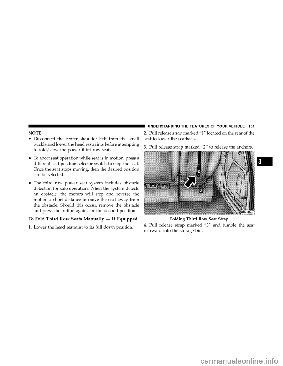
1. Lower the head restraint to its full down position.2. Pull release strap marked “1” located on the rear of the
seat to lower the seatback.
3. Pull release strap marked “2” to release the anchors.
4. Pull release strap marked “3” and tumble the seat
rearward into the storage bin.
Folding Third Row Seat Strap
3
UNDERSTANDING THE FEATURES OF YOUR VEHICLE 151
Page 167 of 538
Lane Change Assist
Tap the lever up or down once, without moving beyond
the detent, and the turn signal (right or left) will flash
three times then automatically turn off.
Turn Signal Warning
If the vehicle electronics sense that the vehicle has
traveled at over 18 mph (29 km/h) for approximately
1 mile (1.6 km) with the turn signals on, a chime will
sound to alert the driver.
High/Low Beam Switch
When the headlights are turned on, pushing the multi-
function lever toward the instrument panel will switch
from low beams to high beams. Pulling back to the
neutral position returns the headlights to the low beam
operation.
Flash-To-Pass
You can signal another vehicle with your headlights by
lightly pulling the multifunction lever toward you. This
will turn on the high beam headlights until the lever is
released.
SmartBeam™ — If Equipped
The SmartBeam™ system provides increased forward
lighting at night by automating high beam control
through the use of a digital camera mounted on the
inside rearview mirror. This camera detects vehicle spe-
cific light and automatically switches from high beams to
low beams until the approaching vehicle is out of view.
To Activate
1. Select “Automatic High Beams — ON” through the
EVIC. Refer to “Electronic Vehicle Information Center
(EVIC)/Customer-Programmable Features” in “Under-
standing Your Instrument Panel” for further information.
166 UNDERSTANDING THE FEATURES OF YOUR VEHICLE
Page 168 of 538
2. Rotate the headlight switch counterclockwise to the
AUTO (A) position.
3. Push the multifunction lever away from you to switch
the headlights to the high beam position. Refer to “Mul-
tifunction Lever” in this section for further information.
NOTE:This system will not activate until the vehicle is
at, or above, 25 mph (40 km/h).
To Deactivate
Perform either of the following steps to deactivate the
SmartBeam™ system.
1. Pull the multifunction lever toward you to switch the
headlights from the high beam to the low beam position.
2. Rotate the headlight switch clockwise from the AUTO
(A) to the on position. NOTE:
Broken, muddy or obstructed headlights and
taillights of vehicles in the field of view will cause
headlights to remain on longer (closer to the vehicle).
Also, dirt, film and other obstructions on the windshield
or camera lens will cause the system to function
improperly.
WINDSHIELD WIPERS AND WASHERS
The wipers and washers are operated by a switch within
the multifunction lever. Rotate the end of the multifunc-
tion lever to select the desired wiper speed.
3
UNDERSTANDING THE FEATURES OF YOUR VEHICLE 167
Page 173 of 538
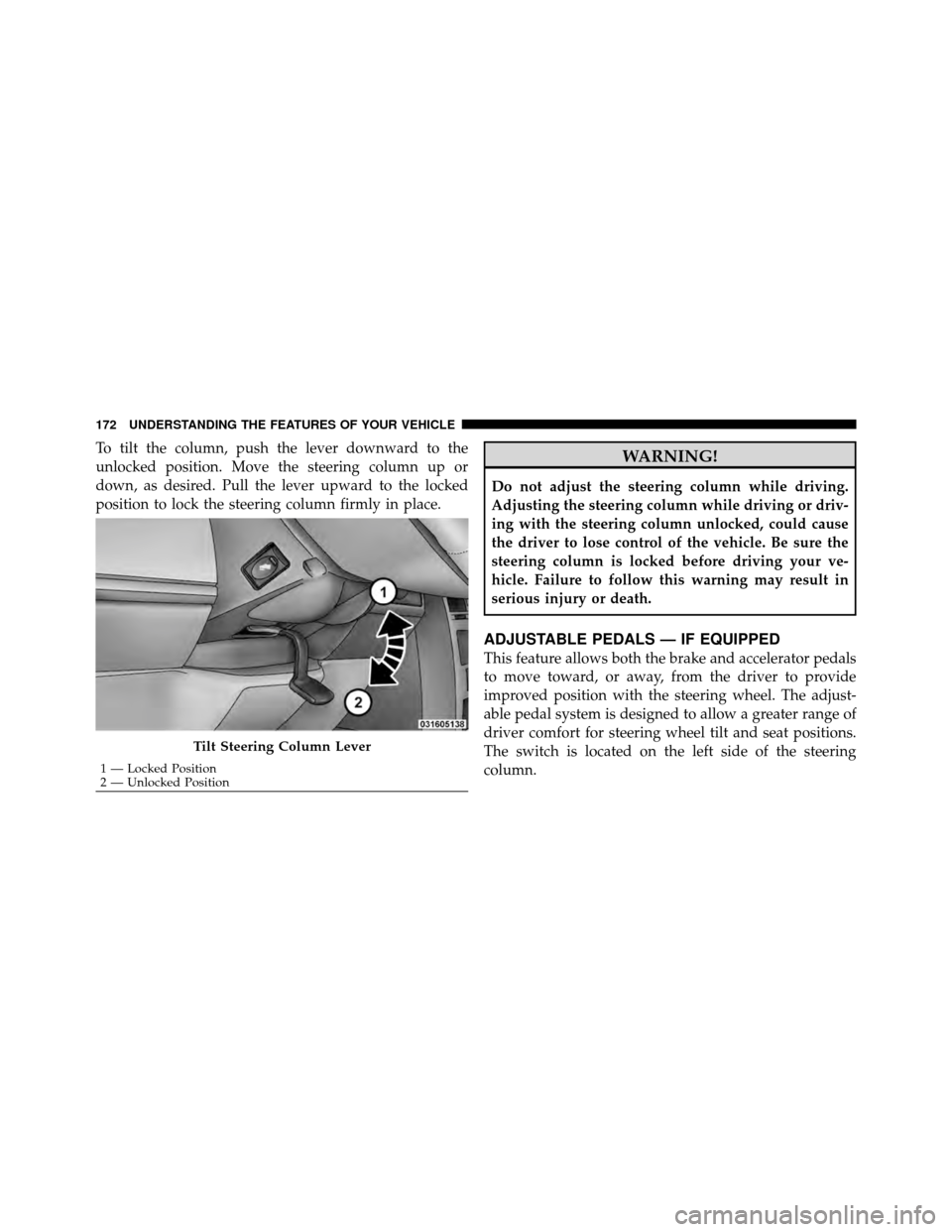
To tilt the column, push the lever downward to the
unlocked position. Move the steering column up or
down, as desired. Pull the lever upward to the locked
position to lock the steering column firmly in place.WARNING!
Do not adjust the steering column while driving.
Adjusting the steering column while driving or driv-
ing with the steering column unlocked, could cause
the driver to lose control of the vehicle. Be sure the
steering column is locked before driving your ve-
hicle. Failure to follow this warning may result in
serious injury or death.
ADJUSTABLE PEDALS — IF EQUIPPED
This feature allows both the brake and accelerator pedals
to move toward, or away, from the driver to provide
improved position with the steering wheel. The adjust-
able pedal system is designed to allow a greater range of
driver comfort for steering wheel tilt and seat positions.
The switch is located on the left side of the steering
column.
Tilt Steering Column Lever
1 — Locked Position
2 — Unlocked Position
172 UNDERSTANDING THE FEATURES OF YOUR VEHICLE
Page 174 of 538
Press the button forward to move the pedals forward
(toward the front of the vehicle).
Press the button rearward to move the pedals rearward
(toward the driver).
•The pedals can be adjusted with the ignition OFF.
•The pedalscannotbe adjusted when the vehicle is in
REVERSE or when the Electronic Speed Control Sys-
tem is on. The following messages will be displayed
on vehicles equipped with the Electronic Vehicle In-
formation System (EVIC) if the pedals are attempted to
be adjusted when the system is locked out (“Adjust-
able Pedal Disabled — Cruise Control Engaged” or
“Adjustable Pedal Disabled — Vehicle In Reverse”.
CAUTION!
Do not place any article under the adjustable pedals
or impede its ability to move, as it may cause damage
to the pedal controls. Pedal travel may become lim-
ited if movement is stopped by an obstruction in the
adjustable pedal’s path.
Adjustable Pedal Switch
3
UNDERSTANDING THE FEATURES OF YOUR VEHICLE 173
Page 177 of 538
Deactivating Electronic Speed Control
A soft tap on the brake pedal or pulling the Electronic
Speed Control lever (CANCEL) toward you will deacti-
vate the Electronic Speed Control without erasing the set
speed memory. Pushing the ON/OFF button to the OFF
position or turning OFF the ignition erases the set speed
memory.
Resuming Speed
To resume a previously set speed, raise the Electronic
Speed Control lever (RESUME ACCEL) upward, and
release. Resume can be used at any speed above 25 mph
(40 km/h).
Varying The Speed Setting
When the Electronic Speed Control is set, you can in-
crease speed by pushing up and holding the RESUME
ACCEL lever. If the lever is continually held in theRESUME ACCEL position, the set speed will continue to
increase until the lever is released, then the new set speed
will be established.
Tapping the Electronic Speed Control lever to RESUME
ACCEL once will result in a 1 mph (1.6 km/h) speed
increase. Each time the lever is tapped speed increases, so
tapping the lever three times will increase speed by
3 mph (4.8 km/h), etc.
To decrease speed while Electronic Speed Control is set,
push down and hold the Electronic Speed Control lever
in SET DECEL. If the lever is continually held in the SET
DECEL position, the set speed will continue to decrease
until the lever is released. Release the lever when the
desired speed is reached, and a new set speed will be
established.
Tapping the Electronic Speed Control lever to SET DE-
CEL once will result in a 1 mph (1.6 km/h) speed
decrease. Each time the lever is tapped, speed decreases.
176 UNDERSTANDING THE FEATURES OF YOUR VEHICLE
Page 187 of 538
WARNING! (Continued)
•Before using the ParkSense�Rear Park Assist
system, it is strongly recommended that the ball
mount and hitch ball assembly is disconnected
from the vehicle when the vehicle is not used for
towing. Failure to do so can result in injury or
damage to vehicles or obstacles because the hitch
ball will be much closer to the obstacle than the
rear fascia when the warning display turns on the
single flashing arc and sounds the continuous
tone. Also, the sensors could detect the ball mount
and hitch ball assembly, depending on its size and
shape, giving a false indication that an obstacle is
behind the vehicle.
PARKVIEW� REAR BACK UP CAMERA — IF
EQUIPPED
Your vehicle may be equipped with the ParkView� Rear
Back Up Camera that allows you to see an on-screen
image of the rear of your vehicle whenever the shift lever
is put into REVERSE. The image will be displayed on the
Navigation/Multimedia radio display screen. The Park-
View� camera is located in the light bar over the rear
license plate.
186 UNDERSTANDING THE FEATURES OF YOUR VEHICLE
Page 216 of 538
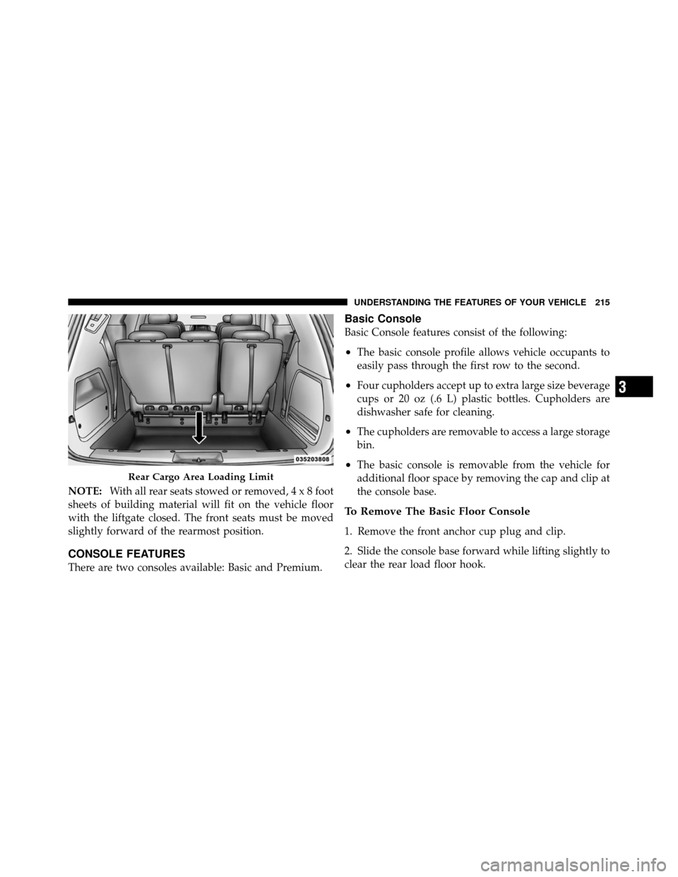
NOTE:With all rear seats stowed or removed,4x8foot
sheets of building material will fit on the vehicle floor
with the liftgate closed. The front seats must be moved
slightly forward of the rearmost position.
CONSOLE FEATURES
There are two consoles available: Basic and Premium.
Basic Console
Basic Console features consist of the following:
•The basic console profile allows vehicle occupants to
easily pass through the first row to the second.
•Four cupholders accept up to extra large size beverage
cups or 20 oz (.6 L) plastic bottles. Cupholders are
dishwasher safe for cleaning.
•The cupholders are removable to access a large storage
bin.
•The basic console is removable from the vehicle for
additional floor space by removing the cap and clip at
the console base.
To Remove The Basic Floor Console
1. Remove the front anchor cup plug and clip.
2. Slide the console base forward while lifting slightly to
clear the rear load floor hook.
Rear Cargo Area Loading Limit
3
UNDERSTANDING THE FEATURES OF YOUR VEHICLE 215