Page 162 of 444

•Door(s) Ajar (with a single chime if vehicle is in
motion)
•Trunk Ajar (with a single chime)
•Headlights On
•Key In Ignition
•Oil Change Required (with a single chime)
•ECO (Fuel Saver Indicator) — If Equipped
Oil Change Required — If Equipped
Your vehicle is equipped with an engine oil change
indicator system. The Oil Change Required message will
flash in the EVIC display for approximately five seconds
after a single chime has sounded to indicate the next
scheduled oil change interval. The engine oil change
indicator system is duty cycle based, which means the
engine oil change interval may fluctuate dependent upon
your personal driving style.Unless reset, this message will continue to display each
time you turn the ignition switch to the ON/RUN
position. To turn off the message temporarily, press and
release the MENU button. To reset the oil change indica-
tor system (after performing the scheduled maintenance)
perform the following procedure:
1. Turn the ignition switch to the ON position (Do not
start the engine).
2. Fully depress the accelerator pedal slowly three times
within 10 seconds.
3. Turn the ignition switch to the LOCK position.
NOTE:
If the indicator message illuminates when you
start the vehicle, the oil change indicator system did not
reset. If necessary repeat this procedure.
4
UNDERSTANDING YOUR INSTRUMENT PANEL 161
Page 163 of 444

Trip Functions
Press and release the MENU button until one of the
following Trip Functions displays in the EVIC:
•ECO (Fuel Saver Indicator) — If Equipped
•Average Fuel Economy
•Distance To Empty
•Elapsed Time
•Display Units of Measure in
Press and release the STEP button to advance the display
through the Trip Functions. The Trip Functions mode displays the following informa-
tion:
•ECO (Fuel Saver Indicator) — If Equipped
The ECO indicator will illuminate in the EVIC display.
This ECO message will appear when you are driving in a
fuel efficient manner and can be used to modify driving
habits in order to increase fuel economy.
•Average Fuel Economy
Shows the average fuel economy since the last reset.
When the fuel economy is reset, the display will read,
RESET or show dashes for two seconds. Then, the history
information will be erased, and the averaging will con-
tinue from the last fuel average reading before the reset.
•Distance To Empty (DTE)
Shows the estimated distance that can be traveled with
the fuel remaining in the tank. This estimated distance is
determined by a weighted average of the instantaneous
162 UNDERSTANDING YOUR INSTRUMENT PANEL
Page 164 of 444

and average fuel economy, according to the current fuel
tank level. DTE cannot be reset through the RESET
button.
NOTE:Significant changes in driving style or vehicle
loading will greatly affect the actual drivable distance of
the vehicle, regardless of the DTE display value.
When the DTE value is less than 30 miles (48 km)
estimated driving distance, the DTE display will change
to a text display of �LOW FUEL”. This display will
continue until the vehicle runs out of fuel. Adding a
significant amount of fuel to the vehicle will turn off the
LOW FUEL text and a new DTE value will display.
•Elapsed Time
Shows the total elapsed time of travel since the last reset.
Elapsed time will increment when the ignition switch is
in the ON or START position.
•Display Units In:
To make your selection, press and release the RESET
button until ENGLISH or METRIC appears.
To Reset The Display
Reset will only occur if a resettable function is currently
displayed. Press and hold the RESET button once to clear
the function currently displayed.
To reset all resettable functions, press and release the
RESET button a second time within three seconds of
resetting the currently displayed function (Reset ALL will
display during this three-second window).
Compass Display
The compass heading indicates the direction
the vehicle is facing. Press and release the
compass button to display one of eight
compass heading and the outside tempera-
ture.
COMPASS
Button
4
UNDERSTANDING YOUR INSTRUMENT PANEL 163
Page 222 of 444

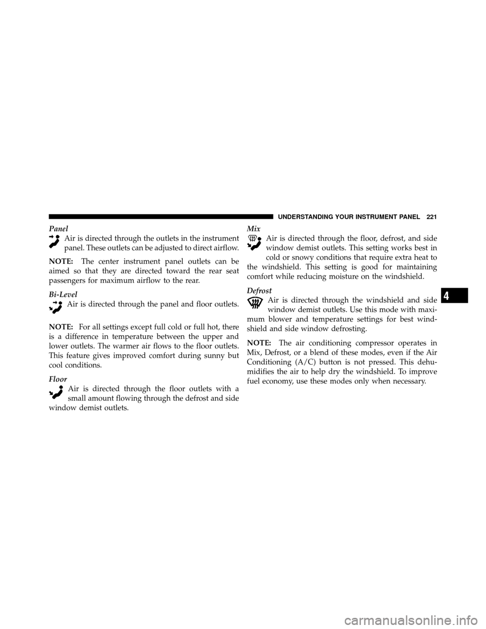
PanelAir is directed through the outlets in the instrument
panel. These outlets can be adjusted to direct airflow.
NOTE: The center instrument panel outlets can be
aimed so that they are directed toward the rear seat
passengers for maximum airflow to the rear.
Bi-Level Air is directed through the panel and floor outlets.
NOTE: For all settings except full cold or full hot, there
is a difference in temperature between the upper and
lower outlets. The warmer air flows to the floor outlets.
This feature gives improved comfort during sunny but
cool conditions.
Floor Air is directed through the floor outlets with a
small amount flowing through the defrost and side
window demist outlets. Mix
Air is directed through the floor, defrost, and side
window demist outlets. This setting works best in
cold or snowy conditions that require extra heat to
the windshield. This setting is good for maintaining
comfort while reducing moisture on the windshield.
Defrost Air is directed through the windshield and side
window demist outlets. Use this mode with maxi-
mum blower and temperature settings for best wind-
shield and side window defrosting.
NOTE: The air conditioning compressor operates in
Mix, Defrost, or a blend of these modes, even if the Air
Conditioning (A/C) button is not pressed. This dehu-
midifies the air to help dry the windshield. To improve
fuel economy, use these modes only when necessary.
4
UNDERSTANDING YOUR INSTRUMENT PANEL 221
Page 236 of 444

▫Tire Inflation Pressures ................ 277
▫ Radial-Ply Tires ..................... 279
▫ Compact Spare Tire ................... 279
▫ Tire Spinning ....................... 280
▫ Tread Wear Indicators ................. 281
▫ Life Of Tire ........................ 282
▫ Replacement Tires .................... 282
� Tire Chains .......................... 283
� Snow Tires .......................... 284
� Tire Rotation Recommendations ........... 284
� Tire Pressure Monitor System (TPMS) ....... 285
▫ Base System ........................ 288
▫ Premium System – If Equipped .......... 290▫
General Information .................. 293
� Fuel Requirements ..................... 294
▫ 2.4L And 2.7L Engine ................. 294
▫ 3.5L Engine ........................ 294
▫ Reformulated Gasoline ................ 295
▫ Gasoline/Oxygenate Blends ............. 295
▫ E-85 Usage In Non-Flex Fuel Vehicles ...... 296
▫ MMT In Gasoline .................... 297
▫ Materials Added To Fuel ............... 297
▫ Fuel System Cautions ................. 297
▫ Carbon Monoxide Warnings ............ 298
� Flexible Fuel (2.7L Only) — If Equipped ..... 299
▫ E85 General Information ............... 299
5
STARTING AND OPERATING 235
Page 237 of 444

▫Ethanol Fuel (E85) ................... 301
▫ Fuel Requirements ................... 301
▫ Selection Of Engine Oil For Flexible Fuel
Vehicles (E85) And Gasoline Vehicles ...... 302
▫ Starting ........................... 302
▫ Cruising Range ...................... 302
▫ Replacement Parts ................... 303
▫ Maintenance ........................ 303
� Adding Fuel ......................... 303
▫ Fuel Filler Cap (Gas Cap) .............. 303
▫ Loose Filler Cap Message .............. 305�
Vehicle Loading ...................... 305
▫ Vehicle Certification Label .............. 305
▫ Gross Vehicle Weight Rating (GVWR) ...... 306
▫ Gross Axle Weight Rating (GAWR) ........ 306
▫ Overloading ........................ 306
▫ Loading ........................... 307
� Trailer Towing ........................ 307
▫ Common Towing Definitions ............ 308
▫ Trailer Hitch Classification .............. 310
▫ Trailer Towing Weights
(Maximum Trailer Weight Ratings) ........ 311
236 STARTING AND OPERATING
Page 240 of 444

motor will continue to run, and it will disengage auto-
matically when the engine is running. If the engine fails
to start, the starter will disengage automatically in 10 sec-
onds. If this occurs, turn the ignition switch to the LOCK
position, wait 10 to 15 seconds, then repeat the “Normal
Starting” procedure.
Extreme Cold Weather (Below�20°F or�29°C)
To ensure reliable starting at these temperatures, use of
an externally powered electric engine block heater (avail-
able from your dealer) is recommended.
If Engine Fails To Start
WARNING!
•Never pour fuel or other flammable liquids into
the throttle body air inlet opening in an attempt to
start the vehicle. This could result in a flash fire
causing serious personal injury.
(Continued)
WARNING! (Continued)
•Do not attempt to push or tow your vehicle to get
it started. Vehicles equipped with an automatic
transmission cannot be started this way. Unburned
fuel could enter the catalytic converter and once
the engine has started, ignite and damage the
converter and vehicle. If the vehicle has a dis-
charged battery, booster cables may be used to
obtain a start from a booster battery or the battery
in another vehicle. This type of start can be dan-
gerous if done improperly. Refer to “Jump Start-
ing” in “What To Do In Emergencies” for further
information.
Without Tip Start
If the engine fails to start after you have followed the
“Normal Starting” or “Extreme Cold Weather” proce-
dures, it may be flooded. Push the accelerator pedal all
5
STARTING AND OPERATING 239
Page 241 of 444

the way to the floor and hold it there while cranking the
engine. This should clear any excess fuel in case the
engine is flooded.
CAUTION!
To prevent damage to the starter, do not crank the
engine for more than 15 seconds at a time. Wait 10 to
15 seconds before trying again.
If the engine is flooded, it may start to run, but not have
enough power to continue running when the key is
released. If this occurs, continue cranking up to 15 sec-
onds with the accelerator pedal pushed all the way to the
floor.
If the engine shows no sign of starting after two 15-
second periods of cranking with the accelerator pedal
held to the floor, repeat the “Normal Starting” or “Ex-
treme Cold Weather” procedures.
With Tip Start
If the engine fails to start after you have followed the
“Normal Starting” or “Extreme Cold Weather” proce-
dures, it may be flooded. To clear any excess fuel, push
the accelerator pedal all the way to the floor and hold it.
Then, turn the ignition switch to the START position and
release it as soon as the starter engages. The starter motor
will disengage automatically in 10 seconds. Once this
occurs, release the accelerator pedal, turn the ignition
switch to the LOCK position, wait 10 to 15 seconds, then
repeat the “Normal Starting” procedure.
CAUTION!
To prevent damage to the starter, wait 10 to 15 sec-
onds before trying again.
After Starting
The idle speed will automatically decrease as the engine
warms up.
240 STARTING AND OPERATING