Page 152 of 465

NOTE:
•The Rain Sensing feature will not operate when the
wiper speed is in the low or high position.
•The Rain Sensing feature may not function properly
when ice or dried salt water is present on the wind-
shield.
•Use of Rain-X�or products containing wax or silicone
may reduce rain sensor performance.
•The Rain Sensing feature can be enabled or disabled.
Refer to “Electronic Vehicle Information Center
(EVIC)/Personal Settings (Customer-Programmable
Features)” in “Understanding Your Instrument Panel”
for further information.
The Rain Sensing system has protective features for the
wiper blades and arms. It will not operate under the
following conditions:
•Low Temperature Wipe Inhibit — The Rain Sensing
feature will not operate when the ignition is placed in
the RUN position, the vehicle is stationary and the
outside temperature is below 32°F (0°C), unless the
wiper control on the multifunction lever is moved, the
vehicle speed becomes greater than 0 mph (0 km/h) or
the outside temperature rises above freezing.
•Neutral Wipe Inhibit — The Rain Sensing feature will
not operate when the ignition is placed in the RUN
position, the transmission shift lever is in the NEU-
TRAL position and the vehicle speed is less than
5 mph (8 km/h), unless the wiper control on the
multifunction lever is moved or the shift lever is
moved out of the NEUTRAL position.
3
UNDERSTANDING THE FEATURES OF YOUR VEHICLE 151
Page 160 of 465
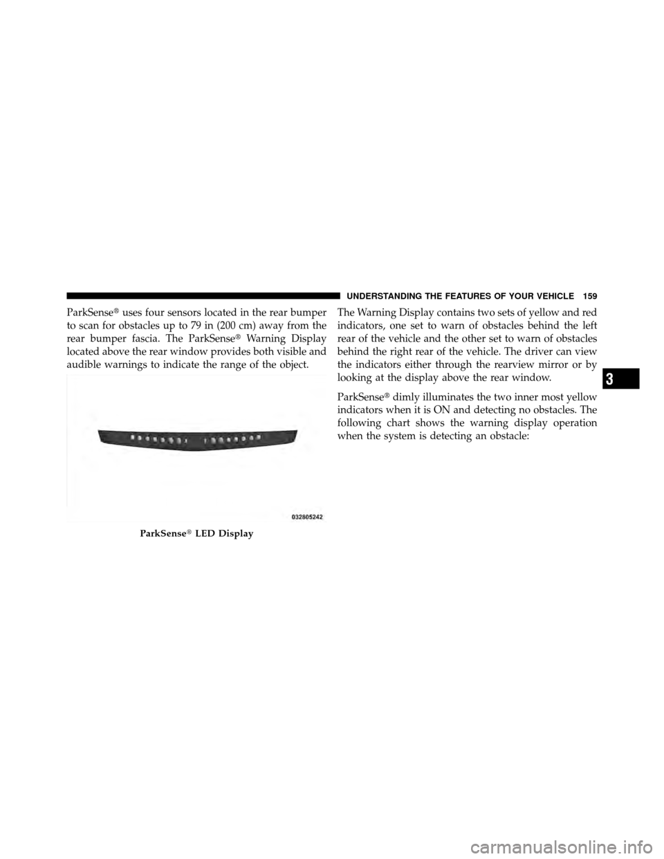
ParkSense�uses four sensors located in the rear bumper
to scan for obstacles up to 79 in (200 cm) away from the
rear bumper fascia. The ParkSense� Warning Display
located above the rear window provides both visible and
audible warnings to indicate the range of the object. The Warning Display contains two sets of yellow and red
indicators, one set to warn of obstacles behind the left
rear of the vehicle and the other set to warn of obstacles
behind the right rear of the vehicle. The driver can view
the indicators either through the rearview mirror or by
looking at the display above the rear window.
ParkSense�
dimly illuminates the two inner most yellow
indicators when it is ON and detecting no obstacles. The
following chart shows the warning display operation
when the system is detecting an obstacle:
ParkSense� LED Display
3
UNDERSTANDING THE FEATURES OF YOUR VEHICLE 159
Page 162 of 465

•When you turn ParkSense�off, the instrument cluster
will display “PARK ASSIST DISABLED.” Further-
more, once you turn ParkSense� off, it remains off
until you turn it on again, even if you cycle the ignition
key.
•When you move the shift lever to the REVERSE
position and ParkSense� is turned off, the instrument
cluster will display “PARK ASSIST DISABLED” mes-
sage for as long as the vehicle is in REVERSE.
•ParkSense�, when on, will MUTE the radio when it is
sounding a tone.
•If a ParkSense� system malfunction occurs, a single
chime will sound once per ignition cycle. In addition,
the Electronic Vehicle Information Center (EVIC) will
display “SERVICE PARK ASSIST SYSTEM” and the
LED in the ParkSense� switch will illuminate. If this
occurs after making sure the rear fascia/bumper is clean and clear of snow, ice, mud, dirt, or other
obstruction, see your authorized dealer for service.
•Clean the ParkSense�
sensors regularly, taking care
not to scratch or damage them. The sensors must not
be covered with ice, snow, slush, mud, dirt, or debris.
Failure to do so can result in ParkSense� not working
properly. The ParkSense� system might not detect an
obstacle behind the fascia/bumper, or it could provide
a false indication that an obstacle is behind the fascia/
bumper.
•Objects must not be within 12 in (30 cm) from the rear
fascia/bumper while driving the vehicle. Failure to do
so can result in the system misinterpreting a close
object as a sensor problem, causing the “SERVICE
PARK ASSIST SYSTEM” message to be displayed in
the instrument cluster.
3
UNDERSTANDING THE FEATURES OF YOUR VEHICLE 161
Page 163 of 465

CAUTION!
•The ParkSense�Rear Park Assist system is only a
parking aid and it is unable to recognize every
obstacle, including small obstacles. Parking curbs
might be temporarily detected or not detected at
all. Obstacles located above or below the sensors
will not be detected when they are in close prox-
imity.
•The vehicle must be driven slowly when using the
ParkSense� Rear Park Assist system to be able to
stop in time when the obstacle is detected. It is
recommended that the driver looks over his/her
shoulder when using ParkSense�.
WARNING!
•Drivers must be careful when backing up even
when using the ParkSense� Rear Park Assist sys-
tem. Always check carefully behind your vehicle,
look behind you, and be sure to check for pedes-
trians, animals, other vehicles, obstructions, and
blind spots before backing up. You are responsible
for safety and must continue to pay attention to
your surroundings. Failure to do so can result in
serious injury or death.
(Continued)
162 UNDERSTANDING THE FEATURES OF YOUR VEHICLE
Page 164 of 465
WARNING! (Continued)
•Before using the ParkSense�Rear Park Assist
system, it is strongly recommended that the ball
mount and hitch ball assembly is disconnected
from the vehicle when the vehicle is not used for
towing. Failure to do so can result in injury or
damage to vehicles or obstacles because the hitch
ball will be much closer to the obstacle than the
rear fascia when the warning display turns on the
single flashing arc and sounds the continuous
tone. Also, the ParkSense� sensors could detect
the ball mount and hitch ball assembly, depending
on its size and shape, giving a false indication that
an obstacle is behind the vehicle.
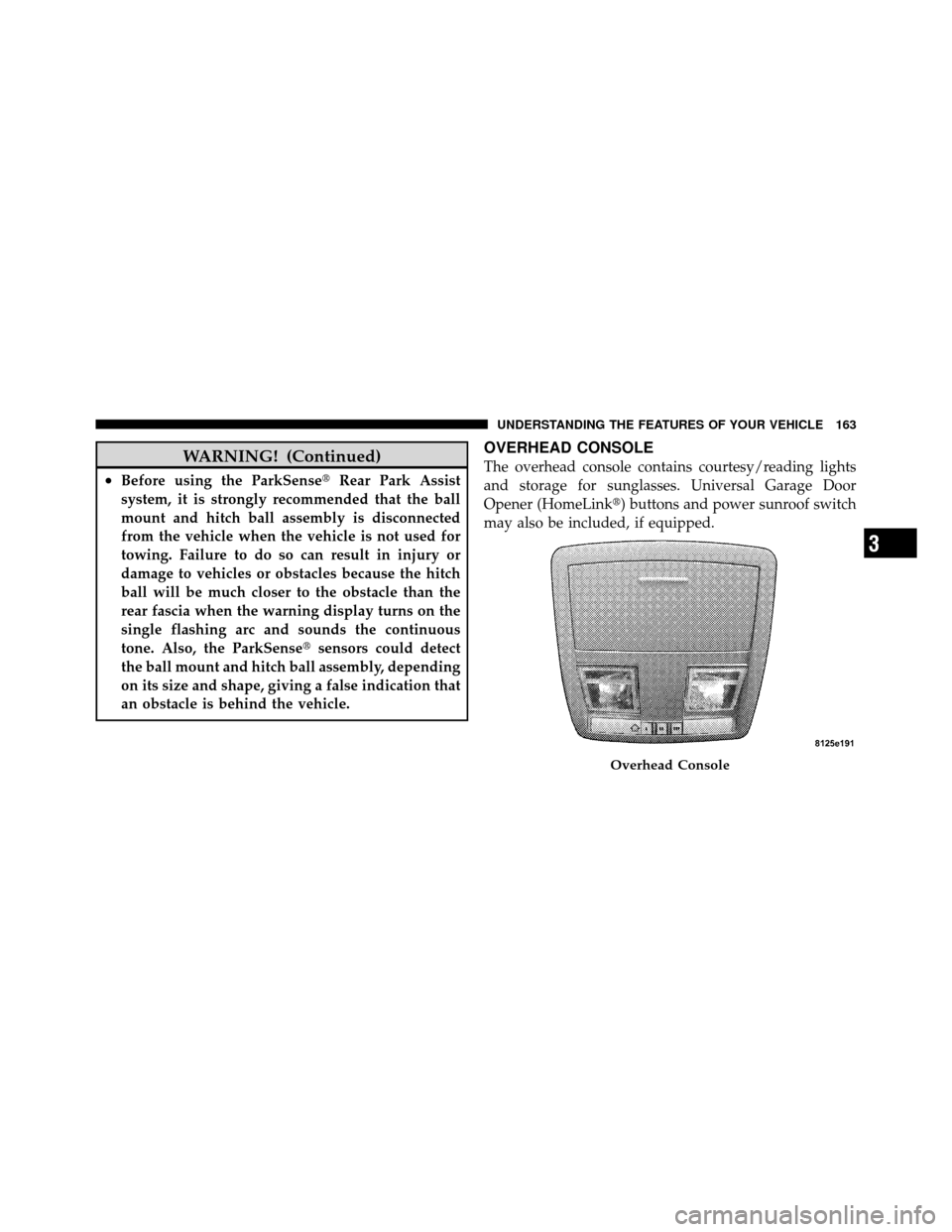
OVERHEAD CONSOLE
The overhead console contains courtesy/reading lights
and storage for sunglasses. Universal Garage Door
Opener (HomeLink�) buttons and power sunroof switch
may also be included, if equipped.
Overhead Console
3
UNDERSTANDING THE FEATURES OF YOUR VEHICLE 163
Page 198 of 465

Your vehicle has also been equipped with a TPMS
malfunction indicator to indicate when the system is not
operating properly. The TPMS malfunction indicator is
combined with the low tire pressure telltale. When the
system detects a malfunction, the telltale will flash for
approximately one minute and then remain continuously
illuminated. This sequence will continue upon subse-
quent vehicle start-ups as long as the malfunction exists.
When the malfunction indicator is illuminated, the sys-
tem may not be able to detect or signal low tire pressure
as intended. TPMS malfunctions may occur for a variety
of reasons, including the installation of replacement or
alternate tires or wheels on the vehicle that prevent the
TPMS from functioning properly. Always check the
TPMS malfunction telltale after replacing one or more
tires or wheels on your vehicle, to ensure that the
replacement or alternate tires and wheels allow the TPMS
to continue to function properly.CAUTION!
The TPMS has been optimized for the original
equipment tires and wheels. TPMS pressures and
warning have been established for the tire size
equipped on your vehicle. Undesirable system opera-
tion or sensor damage may result when using re-
placement equipment that is not of the same size,
type, and/or style. Aftermarket wheels can cause
sensor damage. Do not use tire sealant from a can, or
balance beads if your vehicle is equipped with a
TPMS, as damage to the sensors may result.
23. Charging System Light This light shows the status of the electrical charg-
ing system. The light should come on when the
ignition switch is first placed in the RUN position and
remain on briefly as a bulb check. If the light stays on or
comes on while driving, turn off some of the vehicle’s
4
UNDERSTANDING YOUR INSTRUMENT PANEL 197
Page 215 of 465

3. Press the SCROLL button until “Calibrate Compass”
displays in the EVIC.
4. Press and release the FUNCTION SELECT button to
start the calibration. The message “CAL” will display in
the EVIC.
5. Complete one or more 360 degree turns (in an area free
from large metal or metallic objects) until the “CAL”
message turns off. The compass will now function
normally.
Compass Variance
Compass Variance is the difference between Magnetic
North and Geographic North. To compensate for the
differences, the variance should be set for the zone where
the vehicle is driven, per the zone map. Once properly
set, the compass will automatically compensate for the
differences and provide the most accurate compass head-
ing.NOTE:
Keep magnetic materials away from the top of
the instrument panel, such as iPod’s, Cell Phones, Lap-
tops and Radar Detectors. This is where the compass
module is located, and it can cause interference with the
compass sensor, and it may give false readings.
1. Turn the ignition switch ON.
Compass Variance Map
214 UNDERSTANDING YOUR INSTRUMENT PANEL
Page 266 of 465

After 10 minutes, the system will return to normal AUTO
mode function and the indicator will turn off.
NOTE:
•The surface of the climate control panel and the top
center of the instrument panel should be kept free of
debris due to the location of the climate control
sensors. Mud on the windshield may also cause poor
operation of this system.
•Extended use of recirculation may cause the windows
to fog. If the interior of the windows begin to fog, press
the recirculation button to return to outside air. Some
temp/humidity conditions will cause captured inte-
rior air to condense on windows and hamper visibility.
For this reason, the system will not allow recirculation
to be selected while in Defrost or Defrost/Floor mode.
Attempting to use the recirculation while in these
modes will cause the indicator in the control button to
blink and then turn off.
Manual Operation
This system offers a full complement of manual override
features, which consist of blower preferred automatic,
mode preferred automatic, or blower and mode preferred
automatic. This means the operator can override the
blower, the mode, or both. There is a manual blower
range for times when the AUTO setting is not desired.
The blower can be set to any fixed blower speed by
rotating the blower control knob (on the left).
NOTE:
•For vehicles equipped with Remote Start, the climate
controls will not function during Remote Start opera-
tion if the blower control is left in the “O” (Off)
position.
•Please read the Automatic Temperature Control Op-
eration Chart that follows for details.
4
UNDERSTANDING YOUR INSTRUMENT PANEL 265