Page 343 of 538

power may also be reduced to assist in counteracting the
condition of oversteer or understeer and help the vehicle
maintain the desired path.
The ESP uses sensors in the vehicle to determine the path
that the driver intends to steer the vehicle and compares
it to the actual path of the vehicle. When the actual path
does not match the intended path, the ESP applies the
brake of the appropriate wheel to assist in counteracting
the condition of oversteer or understeer.
•Oversteer - when the vehicle is turning more than
appropriate for the steering wheel position.
•Understeer - when the vehicle is turning less than
appropriate for the steering wheel position.The “ESP/TCS Indicator Light” located in the
instrument cluster, starts to flash as soon as the
tires lose traction and the ESP system becomes
active. The “ESP/TCS Indicator Light” also flashes when the TCS is active. If the “ESP/TCS Indicator
Light” begins to flash during acceleration, ease up on the
accelerator and apply as little throttle as possible. Be sure
to adapt your speed and driving to the prevailing road
conditions.
WARNING!
The ESP cannot prevent the natural laws of physics
from acting on the vehicle, nor can it increase the
traction afforded by prevailing road conditions. The
ESP cannot prevent accidents, including those result-
ing from excessive speed in turns, driving on very
slippery surfaces, or hydroplaning. Only a safe, at-
tentive, and skillful driver can prevent accidents. The
capabilities of an ESP-equipped vehicle must never
be exploited in a reckless or dangerous manner that
could jeopardize the user’s safety or the safety of
others.
342 STARTING AND OPERATING
Page 344 of 538

The ESP system has two available operating modes:
ESP On
This is the normal operating mode for the ESP. Whenever
the vehicle is started, the ESP system will be in this mode.
This mode should be used for most driving conditions.
The ESP should only be turned OFF for specific reasons
as noted in the following paragraphs.
Partial Off
The “Partial Off” mode is intended for times when a
more spirited driving experience is desired. It is also
intended for driving in deep snow, sand, or gravel. This
mode disables the TCS portion of the ESP and raises the
threshold for ESP activation, which allows for more
wheel spin than what ESP normally allows.
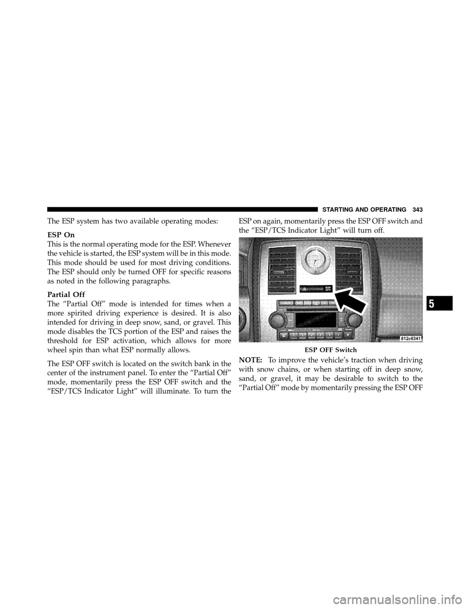
The ESP OFF switch is located on the switch bank in the
center of the instrument panel. To enter the “Partial Off”
mode, momentarily press the ESP OFF switch and the
“ESP/TCS Indicator Light” will illuminate. To turn theESP on again, momentarily press the ESP OFF switch and
the “ESP/TCS Indicator Light” will turn off.
NOTE:
To improve the vehicle’s traction when driving
with snow chains, or when starting off in deep snow,
sand, or gravel, it may be desirable to switch to the
“Partial Off” mode by momentarily pressing the ESP OFF
ESP OFF Switch
5
STARTING AND OPERATING 343
Page 345 of 538

switch. Once the situation requiring “Partial Off” mode is
overcome, turn the ESP on again by momentarily press-
ing the ESP OFF switch. This may be done while the
vehicle is in motion.
Synchronizing ESP
The Malfunction Indicator Light for the ESP is
combined with BAS indicator. If the power
supply is interrupted (battery disconnected or
discharged), the “ESP/BAS Malfunction Indi-
cator Light” may illuminate with the engine running. If
this should occur, turn the steering wheel completely to
the left and then to the right. The “ESP/BAS Malfunction
Indicator Light” should go out. However, if the light
remains on, have the ESP and BAS checked at your
authorized dealer as soon as possible.
ESP/BAS Malfunction Indicator Light and
ESP/TCS Indicator Light
The Malfunction Indicator Light for the ESP is
combined with the BAS indicator. The “ESP/
BAS Malfunction Indicator Light” and the
“ESP/TCS Indicator Light” in the instrument
cluster both come on when the ignition switch is turned
to the ON position. They should go out with the engine
running.
The system will turn the “ESP/BAS Malfunction Indica-
tor Light” on continuously while the engine running if it
detects a malfunction in either the ESP or the BAS or
both. If the light remains on after several ignition switch
cycles, and you have driven the vehicle several miles
(kilometers) at speeds greater than 30 mph (48 km/h),
and the ESP is synchronized (refer to Synchronizing ESP),
see your authorized dealer as soon as possible to have the
problem diagnosed and corrected.
344 STARTING AND OPERATING
Page 346 of 538
NOTE:
•The “ESP/TCS Indicator Light” and the “ESP/BAS
Malfunction Indicator Light” will turn on momen-
tarily each time the ignition switch is turned to the ON
position.
•Each time the ignition switch is turned to the ON
position, the ESP system will be on even if it was
turned off previously.
•The ESP control system will make buzzing or clicking
sounds when it is active. This is NORMAL; the sounds
will stop when ESP becomes inactive following the
maneuver that caused the ESP activation.
TIRE SAFETY INFORMATION
Tire Markings
1 — U.S. DOT Safety Stan-
dards Code (TIN)4 — Maximum Load
2 — Size Designation 5 — Maximum Pressure
3 — Service Description 6 — Treadwear, Traction and Temperature Grades
5
STARTING AND OPERATING 345
Page 349 of 538

EXAMPLE:
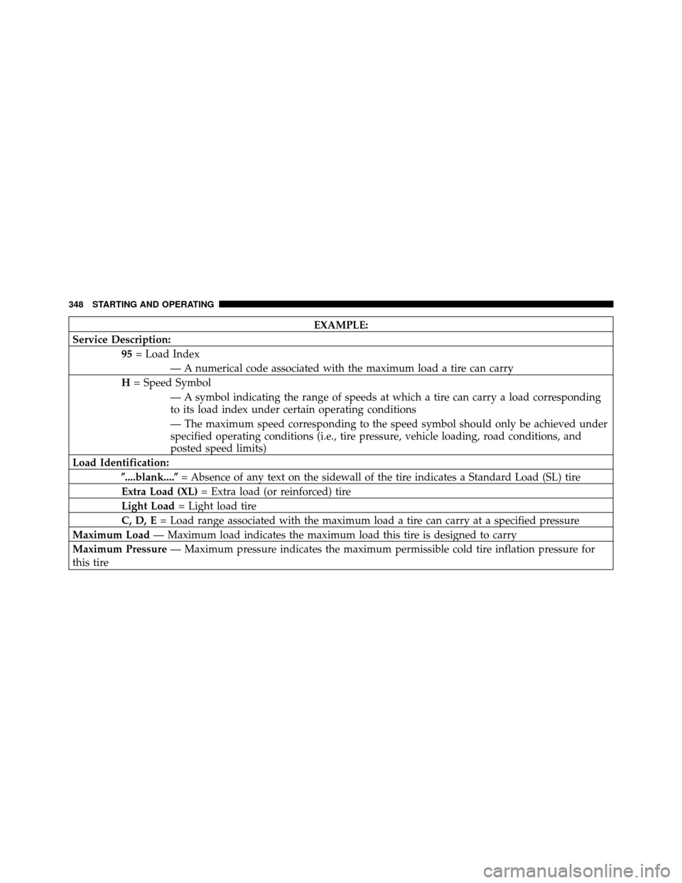
Service Description: 95= Load Index
— A numerical code associated with the maximum load a tire can carry
H = Speed Symbol
— A symbol indicating the range of speeds at which a tire can carry a load corresponding
to its load index under certain operating conditions
— The maximum speed corresponding to the speed symbol should only be achieved under
specified operating conditions (i.e., tire pressure, vehicle loading, road conditions, and
posted speed limits)
Load Identification: \b....blank....\b = Absence of any text on the sidewall of the tire indicates a Standard Load (SL) tire
Extra Load (XL) = Extra load (or reinforced) tire
Light Load = Light load tire
C, D, E = Load range associated with the maximum load a tire can carry at a specified pressure
Maximum Load — Maximum load indicates the maximum load this tire is designed to carry
Maximum Pressure — Maximum pressure indicates the maximum permissible cold tire inflation pressure for
this tire
348 STARTING AND OPERATING
Page 358 of 538

CAUTION!
After inspecting or adjusting the tire pressure, al-
ways reinstall the valve stem cap. This will prevent
moisture and dirt from entering the valve stem,
which could damage the valve stem.
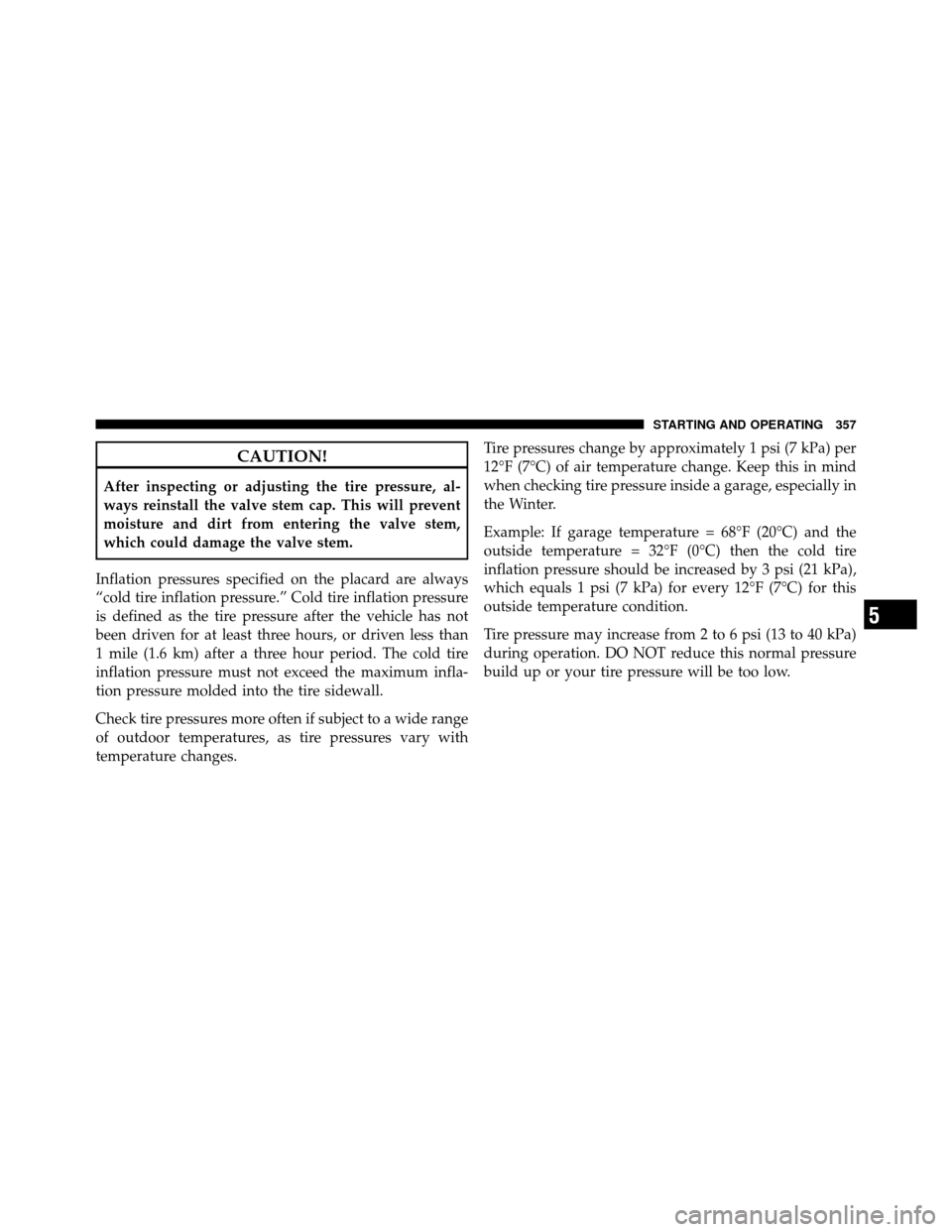
Inflation pressures specified on the placard are always
“cold tire inflation pressure.” Cold tire inflation pressure
is defined as the tire pressure after the vehicle has not
been driven for at least three hours, or driven less than
1 mile (1.6 km) after a three hour period. The cold tire
inflation pressure must not exceed the maximum infla-
tion pressure molded into the tire sidewall.
Check tire pressures more often if subject to a wide range
of outdoor temperatures, as tire pressures vary with
temperature changes. Tire pressures change by approximately 1 psi (7 kPa) per
12°F (7°C) of air temperature change. Keep this in mind
when checking tire pressure inside a garage, especially in
the Winter.
Example: If garage temperature = 68°F (20°C) and the
outside temperature = 32°F (0°C) then the cold tire
inflation pressure should be increased by 3 psi (21 kPa),
which equals 1 psi (7 kPa) for every 12°F (7°C) for this
outside temperature condition.
Tire pressure may increase from 2 to 6 psi (13 to 40 kPa)
during operation. DO NOT reduce this normal pressure
build up or your tire pressure will be too low.
5
STARTING AND OPERATING 357
Page 365 of 538
TIRE ROTATION RECOMMENDATIONS
Tires on the front and rear axles of vehicles operate at
different loads and perform different steering, driving,
and braking functions. For these reasons, they wear at
unequal rates.
These effects can be reduced by timely rotation of tires.
The benefits of rotation are especially worthwhile with
aggressive tread designs such as those on all season type
tires. Rotation will increase tread life, help to maintain
mud, snow and wet traction levels, and contribute to a
smooth, quiet ride.
Refer to “Maintenance Schedule” for the proper mainte-
nance intervals. The reasons for any rapid or unusual
wear should be corrected prior to rotation being per-
formed.The suggested rotation method is the “forward cross”
shown in the following diagram. This rotation pattern
does not apply to some directional tires that must not be
reversed.
Tire Rotation
364 STARTING AND OPERATING
Page 368 of 538

NOTE:
•The TPMS is not intended to replace normal tire care
and maintenance or to provide warning of a tire failure
or condition.
•The TPMS should not be used as a tire pressure gauge
while adjusting your tire pressure.
•Driving on a significantly under-inflated tire causes
the tire to overheat and can lead to tire failure.
Under-inflation also reduces fuel efficiency and tire
tread life, and may affect the vehicle’s handling and
stopping ability.
•The TPMS is not a substitute for proper tire mainte-
nance, and it is the driver ’s responsibility to maintain
correct tire pressure using an accurate tire pressure
gauge, even if under-inflation has not reached the
level to trigger illumination of the TPM Telltale Light.
•Seasonal temperature changes will affect tire pressure,
and the TPMS will monitor the actual tire pressure in
the tire.
Base System
The Tire Pressure Monitor System (TPMS) uses wireless
technology with wheel rim mounted electronic sensors to
monitor tire pressure levels. Sensors mounted to each
wheel as part of the valve stem transmit tire pressure
readings to the receiver module.
NOTE:It is particularly important for you to check the
tire pressure in all of the tires on your vehicle monthly
and to maintain the proper pressure.
The TPMS consists of the following components:
•Receiver module,
•Four TPM sensors, and
•TPM Telltale Light
The matching full size spare wheel and tire assembly (if
equipped) has a TPM sensor. The matching full size spare
can be used in place of any of the four road tires. The
5
STARTING AND OPERATING 367