2010 CHEVROLET SILVERADO power steering
[x] Cancel search: power steeringPage 231 of 626
If the vehicle is started in a dark garage, the automatic
headlamp system comes on immediately. Once the
vehicle leaves the garage, it takes approximately
one minute for the automatic headlamp system to
change to DRL if it is bright enough outside. During that
delay, the instrument panel cluster may not be as bright
as usual. Make sure the instrument panel brightness
control is in the full bright position. SeeInstrument
Panel Brightness on page 4‑14.
To idle the vehicle with the automatic headlamp system
off, turn the control to the off position.
The headlamps will also stay on after you exit the
vehicle. This feature can be programmed using the
Driver Information Center (DIC), if equipped. See DIC
Vehicle Customization (With DIC Buttons)
on
page 4‑73.
If the vehicle is not equipped with DIC buttons, exit
lighting is automatic. When it is dark enough outside,
the exterior lamps remain on for 30 seconds after the
ignition is moved from ON/RUN to LOCK/OFF.
For vehicles without a radio, the instrument panel light
remains on for 30 seconds with the driver's door closed.
For vehicles with a radio, the instrument panel light
remains on for 10 minutes with the driver's door closed.
See Retained Accessory Power (RAP) on page 3‑23.
The regular headlamp system can be turned on when
needed.
Fog Lamps
For vehicles with fog lamps, the control is located next
to the exterior lamps control on the instrument panel, to
the left of the steering column.
The ignition must be in the ON/RUN position for the fog
lamps to come on.
#(Fog Lamps): Press to turn the fog lamps on or off.
A light will come on in the instrument panel cluster.
When the fog lamps are turned on, the parking lamps
automatically turn on.
When the headlamps are changed to high-beam, the
fog lamps also go off. When the high-beam headlamps
are turned off, the fog lamps will come on again.
Some localities have laws that require the headlamps to
be on along with the fog lamps.
4-13
Page 232 of 626
Auxiliary Roof-Mounted Lamp
If the vehicle has this feature, this button includes wiring
provisions for a dealer or a qualified service center to
install an auxiliary roof lamp.
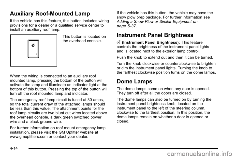
This button is located on
the overhead console.
When the wiring is connected to an auxiliary roof
mounted lamp, pressing the bottom of the button will
activate the lamp and illuminate an indicator light at the
bottom of this button. Pressing the top of the button will
turn off the roof mounted lamp and indicator.
The emergency roof lamp circuit is fused at 30 amps,
so the total current draw of the attached lamps should
be less than this value. The attachment points for the
roof lamp circuits are two blunt cut wires located above
the overhead console, a dark green switched power
wire and a black ground wire.
For further information on roof mount emergency lamp
installation, please visit the GM Upfitter website at
www.gmupfitters.com or contact your dealer. If the vehicle has this button, the vehicle may have the
snow plow prep package. For further information see
Adding a Snow Plow or Similar Equipment
on
page 5‑37.
Instrument Panel Brightness
D (Instrument Panel Brightness): This feature
controls the brightness of the instrument panel lights
and is located next to the exterior lamp control.
Push the knob to extend out and then it can be turned.
Turn the knob clockwise or counterclockwise to brighten
or dim the instrument panel lights. Turning the knob to
the farthest clockwise position turns on the dome lamps.
Dome Lamps
The dome lamps come on when any door is opened.
They turn off after all the doors are closed.
The dome lamps can also be turned on by turning the
instrument panel brightness knob, located on the
instrument panel to the left of the steering column,
clockwise to the farthest position. In this position, the
dome lamps remain on whether a door is opened or
closed.
4-14
Page 371 of 626
Let us say the road is wet and you are driving safely.
Suddenly, an animal jumps out in front of you. You slam
on the brakes and continue braking. Here is what
happens with ABS:
A computer senses that the wheels are slowing down.
If one of the wheels is about to stop rolling, the
computer will separately work the brakes at each front
wheel and at both rear wheels.
ABS can change the brake pressure to each wheel, as
required, faster than any driver could. This can help the
driver steer around the obstacle while braking hard.
As the brakes are applied, the computer keeps
receiving updates on wheel speed and controls braking
pressure accordingly.
Remember: ABS does not change the time needed to
get a foot up to the brake pedal or always decrease
stopping distance. If you get too close to the vehicle in
front of you, there will not be enough time to apply the
brakes if that vehicle suddenly slows or stops. Always
leave enough room up ahead to stop, even with ABS.
Using ABS
Do not pump the brakes. Just hold the brake pedal
down firmly and let antilock work. The brakes might
vibrate or some noise might be heard, but this is
normal.
Braking in Emergencies
ABS allows the driver to steer and brake at the same
time. In many emergencies, steering can help more
than even the very best braking.
Brake Assist (Except With 4.3L V6 Engine)
If this vehicle has StabiliTrak®, it also has a Brake
Assist feature designed to assist the driver in stopping
or decreasing vehicle speed in emergency driving
conditions. This feature uses the stability system
hydraulic brake control module to supplement the power
brake system under conditions where the driver has
quickly and forcefully applied the brake pedal in an
attempt to quickly stop or slow down the vehicle. The
stability system hydraulic brake control module
increases brake pressure at each corner of the vehicle
until the ABS activates. Minor brake pedal pulsations or
pedal movement during this time is normal and the
driver should continue to apply the brake pedal as the
driving situation dictates The Brake Assist feature will
automatically disengage when the brake pedal is
released or brake pedal pressure is quickly decreased.
5-5
Page 374 of 626
In this mode, engine power is not reduced automatically
and the driven wheels can spin more freely. This can
cause the brake-traction control to activate constantly.
Notice:If the wheel(s) of one axle is allowed to spin
excessively while the StabiliTrak, ABS and brake
warning lights and any relevant DIC messages are
displayed, the transfer case could be damaged. The
repairs would not be covered by the vehicle
warranty. Reduce engine power and do not spin the
wheel(s) excessively while these lights and
messages are displayed.
The traction control system may activate on dry or
rough roads or under conditions such as heavy
acceleration while turning or abrupt upshifts/downshifts
of the transmission. When this happens, a reduction in
acceleration may be noticed, or a noise or vibration may
be heard. This is normal.
If cruise control is being used when the system
activates, the StabiliTrak light will flash and cruise
control will automatically disengage. Cruise control may
be reengaged when road conditions allow. See Cruise
Control on page 4‑7.
StabiliTrak may also turn off automatically if it
determines that a problem exists with the system. If the
problem does not clear itself after restarting the vehicle,
see your dealer for service.Locking Rear Axle
Vehicles with a locking rear axle can give more traction
on snow, mud, ice, sand or gravel. It works like a
standard axle most of the time, but when traction is low,
this feature will allow the rear wheel with the most
traction to move the vehicle.
Steering
Power Steering
If the vehicle is a Two‐mode Hybrid, see the Two‐mode
Hybrid manual for more information.
If power steering assist is lost because the engine stops
or the system is not functioning, the vehicle can be
steered but it will take more effort.
Steering Tips
It is important to take curves at a reasonable speed.
Traction in a curve depends on the condition of the tires
and the road surface, the angle at which the curve is
banked, and vehicle speed. While in a curve, speed is
the one factor that can be controlled.
If there is a need to reduce speed, do it before entering
the curve, while the front wheels are straight.
5-8
Page 382 of 626
Approaching a Hill
When you approach a hill, decide if it is too steep to
climb, descend, or cross. Steepness can be hard to
judge. On a very small hill, for example, there may be a
smooth, constant incline with only a small change in
elevation where you can easily see all the way to the
top. On a large hill, the incline may get steeper as you
near the top, but you might not see this because the
crest of the hill is hidden by bushes, grass, or shrubs.
Consider this as you approach a hill:
.Is there a constant incline, or does the hill get
sharply steeper in places?
.Is there good traction on the hillside, or will the
surface cause tire slipping?
.Is there a straight path up or down the hill so you
will not have to make turning maneuvers?
.Are there obstructions on the hill that can block
your path, such as boulders, trees, logs, or ruts?
.What is beyond the hill? Is there a cliff, an
embankment, a drop-off, a fence? Get out and
walk the hill if you do not know. It is the smart way
to find out.
.Is the hill simply too rough? Steep hills often have
ruts, gullies, troughs, and exposed rocks because
they are more susceptible to the effects of erosion.
Driving Uphill
Once you decide it is safe to drive up the hill:
.Use a low gear and get a firm grip on the steering
wheel.
.Get a smooth start up the hill and try to maintain
speed. Not using more power than needed can
avoid spinning the wheels or sliding.
{WARNING:
Turning or driving across steep hills can be
dangerous. You could lose traction, slide
sideways, and possibly roll over. You could be
seriously injured or killed. When driving up hills,
always try to go straight up.
.Try to drive straight up the hill if at all possible.
If the path twists and turns, you might want to find
another route.
.Ease up on the speed as you approach the top of
the hill.
.Attach a flag to the vehicle to be more visible to
approaching traffic on trails or hills.
5-16
Page 444 of 626
Electric Brake Control Wiring
Provisions
These wiring provisions are included with the vehicle as
part of the trailer wiring package. These provisions are
for an electric brake controller. The instrument panel
contains blunt cut wires behind the steering column for
the trailer brake controller. The harness contains the
following wires:
.Dark Blue: Brake Signal to Trailer Connector
.Red/Black: Battery
.Light Blue/White: Brake Switch
.White: Ground
It should be installed by your dealer or a qualified
service center.
If the vehicle is equipped with an ITBC, the blunt cuts
exist, but are not connected further in the harness. If an
aftermarket trailer brake controller is installed, the ITBC
must be disconnected. Do not power both ITBC and
aftermarket controllers to control the trailer brakes at the
same time.
Auxiliary Battery
The auxiliary battery provision can be used to supply
electrical power to additional equipment that may be
added, such as a slide-in camper. If the vehicle has this
provision, this relay will be located on the drivers side of
the vehicle, next to the underhood electrical center.
Be sure to follow the proper installation instructions that
are included with any electrical equipment that is
installed.
Notice: Leaving electrical equipment on for
extended periods will drain the battery. Always
turn off electrical equipment when not in use
and do not use equipment that exceeds the
maximum amperage rating for the auxiliary battery
provision.
5-78
Page 445 of 626
Section 6 Service and Appearance Care
Service. . . . . . . . . . . . . . . . . . . . . . . . . . . . . . . . . . . . . . . . . . . . . 6-4
Accessories and Modifications . . . . . . . . . . . . . . . . . . 6-4
California Proposition 65 Warning . . . . . . . . . . . . . . . 6-5
California Perchlorate Materials Requirements . . . . . . . . . . . . . . . . . . . . . . . . . . . . . . . . . 6-5
Doing Your Own Service Work . . . . . . . . . . . . . . . . . . 6-5
Adding Equipment to the Outside of the Vehicle . . . . . . . . . . . . . . . . . . . . . . . . . . . . . . . . . . . . . . . . 6-6
Fuel . . . . . . . . . . . . . . . . . . . . . . . . . . . . . . . . . . . . . . . . . . . . . . . . . 6-6
Gasoline Octane . . . . . . . . . . . . . . . . . . . . . . . . . . . . . . . . 6-7
Gasoline Specifications . . . . . . . . . . . . . . . . . . . . . . . . . 6-7
California Fuel . . . . . . . . . . . . . . . . . . . . . . . . . . . . . . . . . . 6-8
Additives . . . . . . . . . . . . . . . . . . . . . . . . . . . . . . . . . . . . . . . . 6-8
Fuel E85 (85% Ethanol) . . . . . . . . . . . . . . . . . . . . . . . . . 6-9
Fuels in Foreign Countries . . . . . . . . . . . . . . . . . . . . . 6-11
Filling the Tank . . . . . . . . . . . . . . . . . . . . . . . . . . . . . . . . . 6-11
Filling a Portable Fuel Container . . . . . . . . . . . . . . . 6-13
Checking Things Under the Hood . . . . . . . . . . . . . . .6-14
Hood Release . . . . . . . . . . . . . . . . . . . . . . . . . . . . . . . . . 6-15
Engine Compartment Overview . . . . . . . . . . . . . . . . 6-16
Engine Oil . . . . . . . . . . . . . . . . . . . . . . . . . . . . . . . . . . . . . 6-18
Engine Oil Life System . . . . . . . . . . . . . . . . . . . . . . . . 6-20
Engine Air Cleaner/Filter . . . . . . . . . . . . . . . . . . . . . . . 6-21 Automatic Transmission Fluid (4-Speed
Transmission) . . . . . . . . . . . . . . . . . . . . . . . . . . . . . . . 6-23
Automatic Transmission Fluid (6-Speed Transmission) . . . . . . . . . . . . . . . . . . . . . . . . . . . . . . . 6-26
Cooling System . . . . . . . . . . . . . . . . . . . . . . . . . . . . . . . . 6-29
Engine Coolant . . . . . . . . . . . . . . . . . . . . . . . . . . . . . . . . 6-31
Engine Overheating . . . . . . . . . . . . . . . . . . . . . . . . . . . 6-34
Overheated Engine Protection
Operating Mode . . . . . . . . . . . . . . . . . . . . . . . . . . . . . 6-36
Engine Fan Noise . . . . . . . . . . . . . . . . . . . . . . . . . . . . . 6-37
Power Steering Fluid . . . . . . . . . . . . . . . . . . . . . . . . . . 6-37
Windshield Washer Fluid . . . . . . . . . . . . . . . . . . . . . . 6-38
Brakes . . . . . . . . . . . . . . . . . . . . . . . . . . . . . . . . . . . . . . . . . 6-39
Battery . . . . . . . . . . . . . . . . . . . . . . . . . . . . . . . . . . . . . . . . . 6-43
Jump Starting . . . . . . . . . . . . . . . . . . . . . . . . . . . . . . . . . . 6-44
Rear Axle . . . . . . . . . . . . . . . . . . . . . . . . . . . . . . . . . . . . . . . . . 6-48
Four-Wheel Drive . . . . . . . . . . . . . . . . . . . . . . . . . . . . . . . . . 6-50
Front Axle . . . . . . . . . . . . . . . . . . . . . . . . . . . . . . . . . . . . . . . . . 6-52
Noise Control System . . . . . . . . . . . . . . . . . . . . . . . . . . . . 6-53
Tampering with Noise Control System Prohibited . . . . . . . . . . . . . . . . . . . . . . . . . . . . . . . . . . . 6-53
Headlamp Aiming . . . . . . . . . . . . . . . . . . . . . . . . . . . . . . . . 6-54
6-1
Page 461 of 626

A.Engine Air Cleaner/Filter on page 6‑21.
B. Coolant Surge Tank and Pressure Cap. See Cooling System on page 6‑29.
C. Positive (+) Terminal. See Jump Starting
on
page 6‑44.
D. Battery on page 6‑43.
E. Engine Oil Fill Cap. See “When to Add Engine Oil”
under Engine Oil on page 6‑18.
F. Automatic Transmission Dipstick. See “Checking
the Fluid Level” underAutomatic Transmission
Fluid (4-Speed Transmission)
on page 6‑23or
Automatic Transmission Fluid (6-Speed
Transmission) on page 6‑26.
G. Remote Negative (−) Terminal (Out of View). See Jump Starting on page 6‑44. H. Engine Oil Dipstick (Out of View). See
“Checking
Engine Oil” underEngine Oil on page 6‑18.
I. Engine Cooling Fan. See Cooling System
on
page 6‑29.
J. Power Steering Fluid Reservoir. See Power
Steering Fluid on page 6‑37.
K. Brake Master Cylinder Reservoir. See “Brake
Fluid” under Brakes on page 6‑39.
L. Underhood Fuse Block on page 6‑122.
M. Windshield Washer Fluid Reservoir. See “Adding
Washer Fluid” underWindshield Washer Fluid
on
page 6‑38.
6-17