2010 CHEVROLET SILVERADO display
[x] Cancel search: displayPage 373 of 626
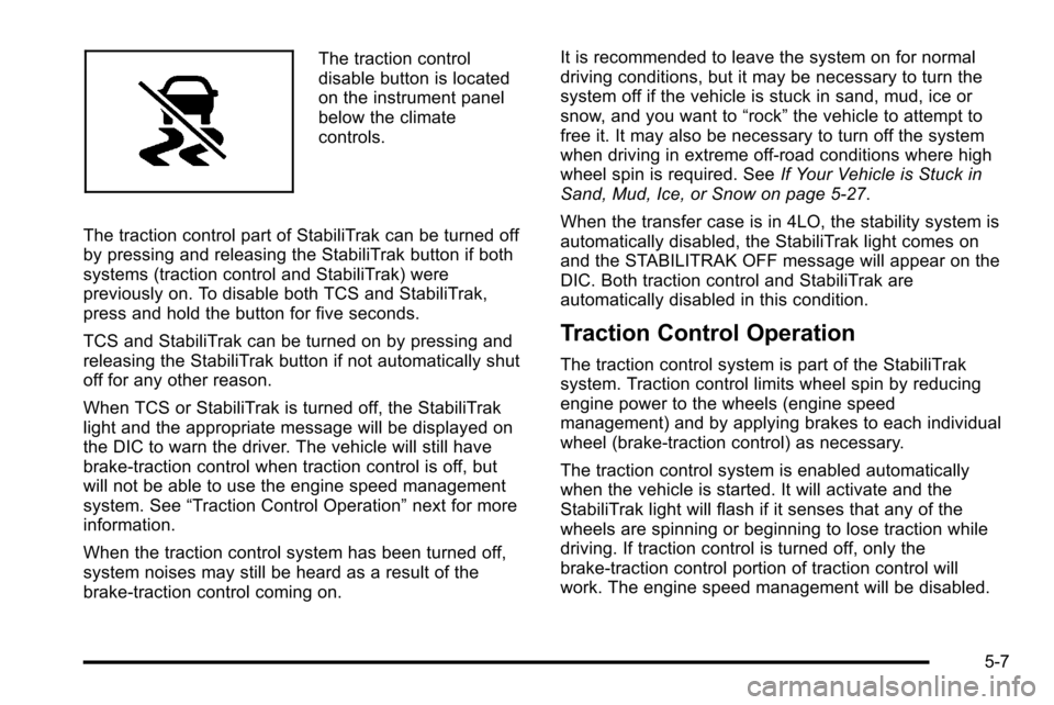
The traction control
disable button is located
on the instrument panel
below the climate
controls.
The traction control part of StabiliTrak can be turned off
by pressing and releasing the StabiliTrak button if both
systems (traction control and StabiliTrak) were
previously on. To disable both TCS and StabiliTrak,
press and hold the button for five seconds.
TCS and StabiliTrak can be turned on by pressing and
releasing the StabiliTrak button if not automatically shut
off for any other reason.
When TCS or StabiliTrak is turned off, the StabiliTrak
light and the appropriate message will be displayed on
the DIC to warn the driver. The vehicle will still have
brake-traction control when traction control is off, but
will not be able to use the engine speed management
system. See “Traction Control Operation” next for more
information.
When the traction control system has been turned off,
system noises may still be heard as a result of the
brake-traction control coming on. It is recommended to leave the system on for normal
driving conditions, but it may be necessary to turn the
system off if the vehicle is stuck in sand, mud, ice or
snow, and you want to
“rock”the vehicle to attempt to
free it. It may also be necessary to turn off the system
when driving in extreme off-road conditions where high
wheel spin is required. See If Your Vehicle is Stuck in
Sand, Mud, Ice, or Snow on page 5‑27.
When the transfer case is in 4LO, the stability system is
automatically disabled, the StabiliTrak light comes on
and the STABILITRAK OFF message will appear on the
DIC. Both traction control and StabiliTrak are
automatically disabled in this condition.
Traction Control Operation
The traction control system is part of the StabiliTrak
system. Traction control limits wheel spin by reducing
engine power to the wheels (engine speed
management) and by applying brakes to each individual
wheel (brake-traction control) as necessary.
The traction control system is enabled automatically
when the vehicle is started. It will activate and the
StabiliTrak light will flash if it senses that any of the
wheels are spinning or beginning to lose traction while
driving. If traction control is turned off, only the
brake-traction control portion of traction control will
work. The engine speed management will be disabled.
5-7
Page 374 of 626
In this mode, engine power is not reduced automatically
and the driven wheels can spin more freely. This can
cause the brake-traction control to activate constantly.
Notice:If the wheel(s) of one axle is allowed to spin
excessively while the StabiliTrak, ABS and brake
warning lights and any relevant DIC messages are
displayed, the transfer case could be damaged. The
repairs would not be covered by the vehicle
warranty. Reduce engine power and do not spin the
wheel(s) excessively while these lights and
messages are displayed.
The traction control system may activate on dry or
rough roads or under conditions such as heavy
acceleration while turning or abrupt upshifts/downshifts
of the transmission. When this happens, a reduction in
acceleration may be noticed, or a noise or vibration may
be heard. This is normal.
If cruise control is being used when the system
activates, the StabiliTrak light will flash and cruise
control will automatically disengage. Cruise control may
be reengaged when road conditions allow. See Cruise
Control on page 4‑7.
StabiliTrak may also turn off automatically if it
determines that a problem exists with the system. If the
problem does not clear itself after restarting the vehicle,
see your dealer for service.Locking Rear Axle
Vehicles with a locking rear axle can give more traction
on snow, mud, ice, sand or gravel. It works like a
standard axle most of the time, but when traction is low,
this feature will allow the rear wheel with the most
traction to move the vehicle.
Steering
Power Steering
If the vehicle is a Two‐mode Hybrid, see the Two‐mode
Hybrid manual for more information.
If power steering assist is lost because the engine stops
or the system is not functioning, the vehicle can be
steered but it will take more effort.
Steering Tips
It is important to take curves at a reasonable speed.
Traction in a curve depends on the condition of the tires
and the road surface, the angle at which the curve is
banked, and vehicle speed. While in a curve, speed is
the one factor that can be controlled.
If there is a need to reduce speed, do it before entering
the curve, while the front wheels are straight.
5-8
Page 434 of 626
The control panel allows adjustment to the amount of
output, referred to as trailer gain, available to the
electric trailer brakes and allows manual application of
the trailer brakes. The Trailer Brake Control Panel is
used along with the Trailer Brake Display Page on the
DIC to adjust and display power output to the trailer
brakes.
Trailer Brake DIC Display Page
The ITBC system displays messages into the vehicle’s
Driver Information Center (DIC). SeeDIC Warnings and
Messages
on page 4‑63for more information.
The display page indicates Trailer Gain setting, power
output to the electric trailer brakes, trailer connection
and system operational status.
The Trailer Brake Display Page can be displayed by
performing any of the following actions:
.Scrolling through the DIC menu pages using the
odometer trip stem or the DIC Vehicle Information
button (if equipped).
.Pressing a Trailer Gain button –If the Trailer Brake
Display Page is not currently displayed, pressing a
Trailer Gain button will first recall the current Trailer
Gain setting. After the Trailer Brake Display Page
is displayed, each press and release of the gain
buttons will then cause the Trailer Gain setting to
change.
.Activating the Manual Trailer Brake Apply lever
.Connecting a trailer equipped with electric trailer
brakes
All DIC warning and service messages must first be
acknowledged by the driver by pressing the odometer
trip stem or the DIC Vehicle Information button (if
equipped) before the Trailer Brake Display Page can be
displayed and Trailer Gain can be adjusted.
TRAILER GAIN –This setting is displayed anytime the
Trailer Brake Display Page is active. This setting can be
adjusted from 0.0 to 10.0 with either a trailer connected
or disconnected. To adjust the Trailer Gain, press one of
the Trailer Gain adjustment buttons located on the
Trailer Brake Control Panel. Press and hold a gain
button to cause the Trailer Gain to continuously adjust.
To turn the output to the trailer off, adjust the Trailer
Gain setting to 0.0 (zero).
0.0 (zero) gain is the factory default setting. To properly
adjust trailer gain, see the Trailer Gain Adjustment
Procedure later in this section.
TRAILER OUTPUT –This is displayed any time a trailer
with electric brakes is connected. Output to the electric
brakes is based on the amount of vehicle braking
present and relative to the Trailer Gain setting. Output is
displayed from 0 to 10 bars for each gain setting.
5-68
Page 435 of 626
The Trailer Output will indicate“- - - - - -“on the Trailer
Brake Display Page whenever the following occur:
.No trailer is connected.
.A trailer without electric brakes is connected (no
DIC message is displayed).
.A trailer with electric brakes has become
disconnected (a CHECK TRAILER WIRING
message will also be displayed on the DIC).
.There is a fault present in the wiring to the electric
trailer brakes (a CHECK TRAILER WIRING
message will also be displayed on the DIC).
.There is a fault in the ITBC system (a SERVICE
TRAILER BRAKE SYSTEM message will also be
displayed in the DIC).
Manual Trailer Brake Apply
The Manual Trailer Brake Apply Lever is located on the
Trailer Brake Control Panel and is used to apply the
trailer ’s electric brakes independent of the vehicle’ s
brakes. This lever is used in the Trailer Gain Adjustment
Procedure to properly adjust the power output to the
trailer brakes. Sliding the lever to the left will apply only
the trailer brakes. The power output to the trailer is
indicated in the Trailer Brake Display Page in the DIC.
If the vehicle’s service brakes are applied while using
the Manual Trailer Brake Apply Lever, the trailer output
power will be the greater of the two. The trailer and the vehicle's brake lamps will come on
when either vehicle braking or manual trailer brakes are
applied.
Trailer Gain Adjustment Procedure
Trailer Gain should be set for a specific trailering
condition and must be adjusted any time vehicle
loading, trailer loading or road surface conditions
change.
Setting the Trailer Gain properly is needed for the best
trailer stopping performance. A trailer that is
over-gained may result in locked trailer brakes. A trailer
that is under-gained may result in not enough trailer
braking. Both of these conditions may result in poorer
stopping and stability of the vehicle and trailer.
Use the following procedure to correctly adjust Trailer
Gain for each towing condition:
1. Make sure the trailer brakes are in proper working condition.
2. Connect a properly loaded trailer to the vehicle and make all necessary mechanical and electrical
connections. See Loading the Vehicle
on
page 5‑29for more information.
5-69
Page 436 of 626
3. After the electrical connection is made to a trailerequipped with electric brakes:
.A TRAILER CONNECTED message will be
briefly displayed on the DIC display.
.The Trailer Brake Display Page will appear on
the DIC showing TRAILER GAIN and TRAILER
OUTPUT.
.In the Trailer Output display on the
DIC, “- - - - - -“ will disappear if there is no
error present. Connecting a trailer without
electric brakes will not clear the six dashed
lines.
4. Adjust the Trailer Gain by using the gain adjustment (+ / -) buttons on the Trailer Brake
Control Panel.
5. Drive the vehicle with the trailer attached on a level road surface representative of the towing condition
and free of traffic at about 20 to 25 mph (32 to
40 km/h) and fully apply the Manual Trailer Brake
Apply lever.
Adjusting trailer gain at speeds lower than 20 to
25 mph (32 to 40 km/h) may result in an incorrect
gain setting. 6. Adjust the Trailer Gain to just below the point of
trailer wheel lock-up, indicated by trailer wheel
squeal or tire smoke when a trailer wheel locks.
Trailer wheel lock-up may not occur if towing a
heavily loaded trailer. In this case, adjust the
Trailer Gain to the highest allowable setting for the
towing condition.
7. Re-adjust Trailer Gain any time vehicle loading, trailer loading or road surface conditions change or
if trailer wheel lock-up is noticed at any time while
towing.
Other ITBC Related DIC Messages
In addition to displaying TRAILER GAIN and TRAILER
OUTPUT through the DIC, trailer connection and ITBC
system status is displayed in the DIC.
TRAILER CONNECTED –This message will be briefly
displayed when a trailer with electric brakes is first
connected to the vehicle. This message will
automatically turn off in about ten seconds. The driver
can also acknowledge this message before it
automatically turns off.
5-70
Page 437 of 626
CHECK TRAILER WIRING–This message will be
displayed if:
1. The ITBC system first determines connection to a trailer with electric brakes and then the trailer
harness becomes disconnected from the vehicle.
If the disconnect occurs while the vehicle is
stationary, this message will automatically turn off
in about thirty seconds. This message will also turn
off if the driver acknowledges this message off or if
the trailer harness is re-connected.
If the disconnect occurs while the vehicle is
moving, this message will continue until the ignition
is turned off. This message will also turn off if the
driver acknowledges this message off or if the
trailer harness is re-connected.
2. There is an electrical fault in the wiring to the electric trailer brakes. This message will continue
as long as there is an electrical fault in the trailer
wiring. This message will also turn off if the driver
acknowledges this message off.
To determine if the electrical fault is on the vehicle side
or trailer side of the trailer wiring harness connection,
do the following: 1. Disconnect the trailer wiring harness from the vehicle.
2. Turn the ignition OFF. 3. Wait ten seconds, then turn the ignition back
to RUN.
4. If the CHECK TRAILER WIRING message re-appears, the electrical fault is on the
vehicle side.
If the CHECK TRAILER WIRING message only
re-appears when connecting the trailer wiring
harness to the vehicle, the electrical fault is on the
trailer side.
SERVICE TRAILER BRAKE SYSTEM –This message
will be displayed when there is a problem with the ITBC
system. If this message persists over multiple ignition
cycles there is a problem with the ITBC system. Take
the vehicle to an authorized GM dealer to have the
ITBC system diagnosed and repaired.
If either the CHECK TRAILER WIRING or SERVICE
TRAILER BRAKE SYSTEM message is displayed while
driving the vehicle, power is no longer available to the
trailer brakes. When traffic conditions allow, carefully
pull the vehicle over to the side of the road and turn the
ignition off. Check the wiring connection to the trailer
and turn the ignition back on. If either of these
messages continues, either the vehicle or trailer needs
service.
5-71
Page 457 of 626
The TIGHTEN GAS CAP message displays on the
Driver Information Center (DIC) if the fuel cap is not
properly installed. SeeDIC Warnings and Messages
on
page 4‑63for more information.
{WARNING:
If a fire starts while you are refueling, do not
remove the nozzle. Shut off the flow of fuel by
shutting off the pump or by notifying the station
attendant. Leave the area immediately.
Notice: If you need a new fuel cap, be sure to get
the right type. Your dealer can get one for you.
If you get the wrong type, it may not fit properly.
This may cause the malfunction indicator lamp to
light and may damage the fuel tank and emissions
system. See Malfunction Indicator Lamp
on
page 4‑41.
Filling a Portable Fuel Container
{WARNING:
Never fill a portable fuel container while it is in the
vehicle. Static electricity discharge from the
container can ignite the fuel vapor. You can be
badly burned and the vehicle damaged if this
occurs. To help avoid injury to you and others:
.Dispense fuel only into approved containers.
.Do not fill a container while it is inside a
vehicle, in a vehicle's trunk, pickup bed, or on
any surface other than the ground.
.Bring the fill nozzle in contact with the inside
of the fill opening before operating the nozzle.
Contact should be maintained until the filling is
complete.
.Do not smoke while pumping fuel.
.Do not use a cellular phone while
pumping fuel.
6-13
Page 465 of 626
Always reset the engine oil life to 100% after every oil
change. It will not reset itself. To reset the Engine Oil
Life System on most vehicles:1. Display the OIL LIFE REMAINING on the DIC. If the vehicle does not have DIC buttons, the
vehicle must be in P (Park) to access this display.
See DIC Operation and Displays (With DIC
Buttons)
on page 4‑49or DIC Operation and
Displays (Without DIC Buttons) on page 4‑56.
2. Press and hold the SET/RESET button on the DIC, or the trip odometer reset stem if the vehicle does
not have DIC buttons, for more than five seconds.
The oil life will change to 100%.
On all vehicles, the Engine Oil Life System can be reset
as follows: 1. Turn the ignition to ON/RUN with the engine off
2. Fully press the accelerator pedal slowly three times within five seconds.
3. Display the OIL LIFE REMAINING on the DIC. If the display shows 100%, the system is reset.
See DIC Operation and Displays (With DIC
Buttons)
on page 4‑49or DIC Operation and
Displays (Without DIC Buttons) on page 4‑56. If the vehicle has a CHANGE ENGINE OIL SOON
message and it comes back on when the vehicle is
started and/or the OIL LIFE REMAINING is near 0%,
the Engine Oil Life System has not reset. Repeat the
procedure.
What to Do with Used Oil
Used engine oil contains certain elements that can be
unhealthy for your skin and could even cause cancer.
Do not let used oil stay on your skin for very long. Clean
your skin and nails with soap and water, or a good hand
cleaner. Wash or properly dispose of clothing or rags
containing used engine oil. See the manufacturer's
warnings about the use and disposal of oil products.
Used oil can be a threat to the environment. If you
change your own oil, be sure to drain all the oil from the
filter before disposal. Never dispose of oil by putting it in
the trash, pouring it on the ground, into sewers, or into
streams or bodies of water. Recycle it by taking it to a
place that collects used oil.
Engine Air Cleaner/Filter
If the vehicle has a diesel engine, see
“Pickup Models”
under “Engine Air Cleaner/Filter” in the DURAMAX®
Diesel Supplement for the correct inspection and
replacement procedures.
SeeEngine Compartment Overview
on page 6‑16for
the location of the engine air cleaner/filter.
6-21