2010 CHEVROLET HHR display
[x] Cancel search: displayPage 181 of 480
Electric Power Management
This vehicle has Electric Power Management (EPM),
an advanced control system. It estimates the battery's
temperature and state of charge and then adjusts the
voltage for best performance and extended life of the
battery.
When the battery's state of charge is low, the voltage is
raised slightly to quickly put the charge back in. When
the state of charge is high, the voltage is lowered
slightly to prevent overcharging. If the vehicle has a
voltmeter gauge or voltage display on the Driver
Information Center (DIC), you may see the voltage
move up or down. This is normal. If there is a problem,
an alert will be displayed.
The battery can be discharged at idle if the electrical
loads are very high. This is true for all vehicles. This is
because the generator (alternator) may not be spinning
fast enough at idle to produce all the power that is
needed for very high electrical loads.
A high electrical load occurs when several of the
following loads are on: headlamps, high beams, fog
lamps, rear window defogger, climate control fan at high
speed, heated seats, engine cooling fans, trailer loads,
and loads plugged into accessory power outlets.EPM works to prevent excessive discharge of the
battery. It does this by balancing the generator's output
and the vehicle's electrical needs. It can increase
engine idle speed to generate more power, whenever
needed. It can temporarily reduce the power demands
of some accessories.
Normally, these actions occur in steps or levels, without
being noticeable. In rare cases at the highest levels of
corrective action, this action may be noticeable to the
driver.
Battery Run-Down Protection
The vehicle has a battery saver feature designed to
protect the vehicle's battery.
When any interior lamp is left on and the ignition is
turned off, the battery rundown protection system
automatically turns the lamp off after 20 minutes.
This prevents draining of the battery.
4-15
Page 191 of 480
Speedometer and Odometer
The speedometer shows the speed in both kilometers
per hour (km/h) and miles per hour (mph).
The vehicle's odometer works together with the Driver
Information Center (DIC). Trip A and Trip B can be set
on the odometer. See“Trip Information”underDIC
Operation and Displays on page 4‑46.
The vehicle does not have to be running to check the
odometer mileage. Simply open the driver's door and
the mileage briefly displays.
If the vehicle ever needs a new odometer installed, the
new one will be set to the correct total mileage of the
old odometer.
Tachometer
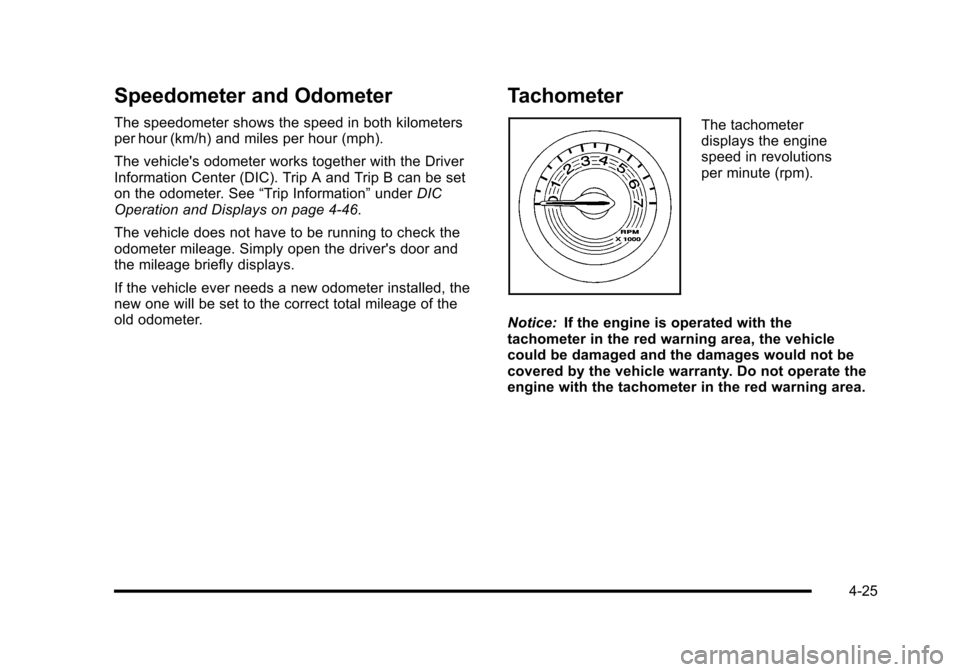
The tachometer
displays the engine
speed in revolutions
per minute (rpm).
Notice: If the engine is operated with the
tachometer in the red warning area, the vehicle
could be damaged and the damages would not be
covered by the vehicle warranty. Do not operate the
engine with the tachometer in the red warning area.
4-25
Page 207 of 480
This gauge displays the air pressure level in the intake
manifold before it enters the engine's combustion
chamber.
It is automatically centered at zero every time the
engine is started. Actual vacuum or boost is displayed
from this zero point. Changes in ambient pressure, such
as driving in mountains and changing weather, will
slightly change the zero reading.
Reconfigurable Performance
Display (RPD)
For vehicles with the RPD, the screen displays
information that can be used to monitor vehicle
performance. The RPD knob located next to the screen
is used to configure the display and select information
to be viewed.
A short video plays whenever the ignition key is turned
on. Press the RPD knob to stop the video and go
directly to RPD displays.
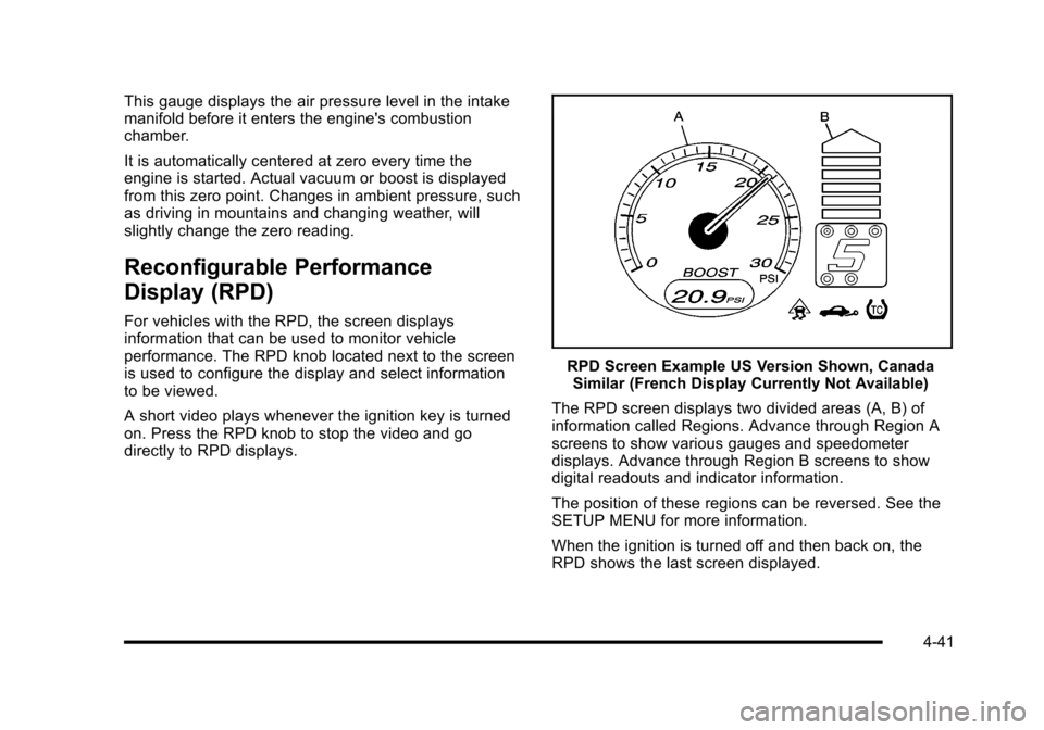
RPD Screen Example US Version Shown, CanadaSimilar (French Display Currently Not Available)
The RPD screen displays two divided areas (A, B) of
information called Regions. Advance through Region A
screens to show various gauges and speedometer
displays. Advance through Region B screens to show
digital readouts and indicator information.
The position of these regions can be reversed. See the
SETUP MENU for more information.
When the ignition is turned off and then back on, the
RPD shows the last screen displayed.
4-41
Page 208 of 480

Region A Gauge and Speedometer
Displays
Change the information displayed in Region A by
turning the knob either clockwise or counterclockwise.
The available gauges are:
BOOST:Displays positive boost pressure as
determined by the manifold air pressure (MAP) sensor.
AIR/FUEL RATIO: Displays the mass ratio of air to fuel.
CAM PHASER ANGLES: Displays orientation of the
intake and exhaust cam shafts relative to their park
positions as commanded by the engine control module.
OVERLAP represents the total distance the intake and
exhaust cam shafts have phased.
SPARK ADVANCE/ KNOCK RETARD: The spark
advance gauge displays ignition timing. Knock retard
indicates the amount of ignition delay to reduce spark
knock.
ENGINE POWER & TORQUE : Displayed engine
power and torque are engine flywheel output values
calculated by the engine control module. These
values are approximate and may change with the air
conditioning load, generator output, air temperature, air
pressure, and fuel octane. SPEEDOMETER & G FORCE :
The G FORCE meter
displays lateral acceleration. While turning right,
G forces are felt on the left, and vice versa. PEAK
values are stored indefinitely, and can be reset with
a press and hold of the RPD knob while viewing the
G FORCE meter.
SETUP MENU: Press the RPD knob to enter this
menu. The vehicle should be stopped while configuring
the setup menu selections.
SCREEN OFF: Turns the screen off.
Region B Readout Displays
Press the RPD knob to highlight Region B. The
information displayed can be changed by turning the
RPD knob either clockwise or counterclockwise.
Press the RPD knob again, to store the selection. The
selection will also be stored after a few seconds of no
activity. Available modes are:
Readouts #1
SHIFT LIGHTS/GEAR INDICATION: The shift lights
provide visual identification of engine speed for a
transmission gear. Shift light minimum and maximum
RPM settings can be viewed and configured in the
SETUP screen. The gear indication on manual
transmission vehicles is calculated by the engine
control module. The gear is only displayed when
enough torque is available to determine the selected
forward gear.
4-42
Page 209 of 480
Readouts #2
TIRE PRESSURES:Displays the last gauge tire
pressures recorded from each of the wheel mounted tire
pressure sensors.
Readouts #3
BAROMETER: Displays ambient air pressure as
measured by the engine’s ambient pressure sensor.
OUTSIDE TEMPERATURE: Displays ambient
temperature as measured by an outside air temperature
sensor.
BATTERY VOLTAGE: Displays the vehicle’s battery
voltage.
Readouts #4
COOLANT TEMPERATURE: Displays engine coolant
temperature as measured by a coolant temperature
sensor.
INLET AIR TEMPERATURE: Displays the
instantaneous temperature of the air at the inlet to the
induction system. FUEL PRESSURE:
Displays fuel pressure as
measured by a sensor on the output of the
high-pressure fuel pump.
INDICATORS
The indicators come on when the corresponding
function is actively working to stabilize or control the
vehicle. Each indicator light on the RPD display can be
turned on and off using the SETUP MENU. These
indicators work independently of the telltales on the
instrument panel cluster. Turning the indicator on the
RPD display on or off does not enable or disable the
functions on the vehicle.
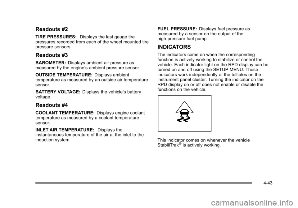
This indicator comes on whenever the vehicle
StabiliTrak®is actively working.
4-43
Page 210 of 480
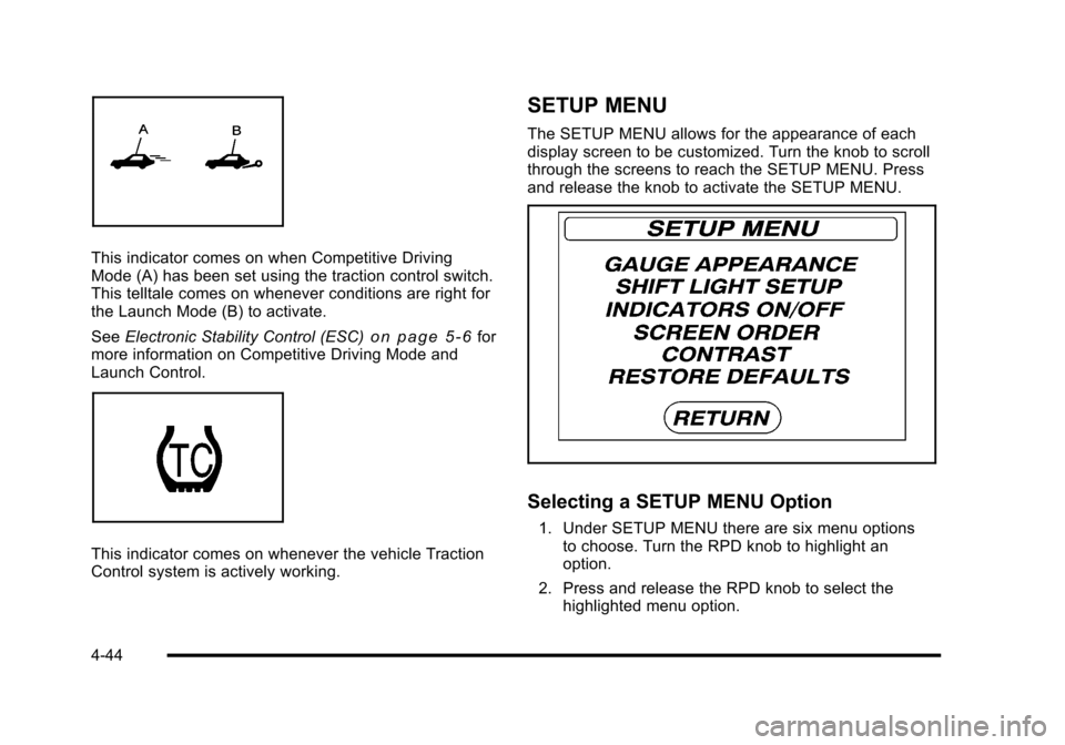
This indicator comes on when Competitive Driving
Mode (A) has been set using the traction control switch.
This telltale comes on whenever conditions are right for
the Launch Mode (B) to activate.
SeeElectronic Stability Control (ESC)
on page 5‑6for
more information on Competitive Driving Mode and
Launch Control.
This indicator comes on whenever the vehicle Traction
Control system is actively working.
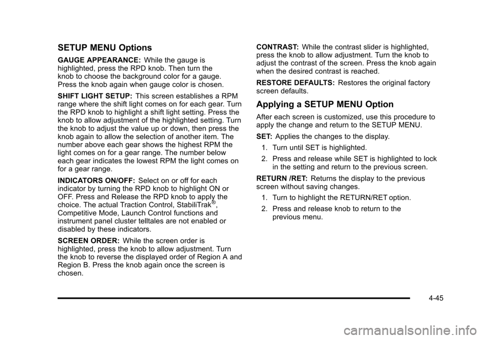
SETUP MENU
The SETUP MENU allows for the appearance of each
display screen to be customized. Turn the knob to scroll
through the screens to reach the SETUP MENU. Press
and release the knob to activate the SETUP MENU.
Selecting a SETUP MENU Option
1. Under SETUP MENU there are six menu options to choose. Turn the RPD knob to highlight an
option.
2. Press and release the RPD knob to select the highlighted menu option.
4-44
Page 211 of 480
SETUP MENU Options
GAUGE APPEARANCE:While the gauge is
highlighted, press the RPD knob. Then turn the
knob to choose the background color for a gauge.
Press the knob again when gauge color is chosen.
SHIFT LIGHT SETUP: This screen establishes a RPM
range where the shift light comes on for each gear. Turn
the RPD knob to highlight a shift light setting. Press the
knob to allow adjustment of the highlighted setting. Turn
the knob to adjust the value up or down, then press the
knob again to allow the selection of another item. The
number above each gear shows the highest RPM the
light comes on for a gear range. The number below
each gear indicates the lowest RPM the light comes on
for a gear range.
INDICATORS ON/OFF: Select on or off for each
indicator by turning the RPD knob to highlight ON or
OFF. Press and Release the RPD knob to apply the
choice. The actual Traction Control, StabiliTrak
®,
Competitive Mode, Launch Control functions and
instrument panel cluster telltales are not enabled or
disabled by these indicators.
SCREEN ORDER: While the screen order is
highlighted, press the knob to allow adjustment. Turn
the knob to reverse the displayed order of Region A and
Region B. Press the knob again once the screen is
chosen. CONTRAST:
While the contrast slider is highlighted,
press the knob to allow adjustment. Turn the knob to
adjust the contrast of the screen. Press the knob again
when the desired contrast is reached.
RESTORE DEFAULTS: Restores the original factory
screen defaults.
Applying a SETUP MENU Option
After each screen is customized, use this procedure to
apply the change and return to the SETUP MENU.
SET: Applies the changes to the display.
1. Turn until SET is highlighted.
2. Press and release while SET is highlighted to lock in the setting and return to the previous screen.
RETURN /RET: Returns the display to the previous
screen without saving changes.
1. Turn to highlight the RETURN/RET option.
2. Press and release knob to return to the previous menu.
4-45
Page 212 of 480
Driver Information Center (DIC)
Your vehicle has a Driver Information Center (DIC). The
DIC display gives you the status of many of your
vehicle's systems. The DIC is also used to display
driver personalization menu modes and warning/status
messages. All messages will appear in the DIC display,
located at the bottom of the instrument panel cluster.
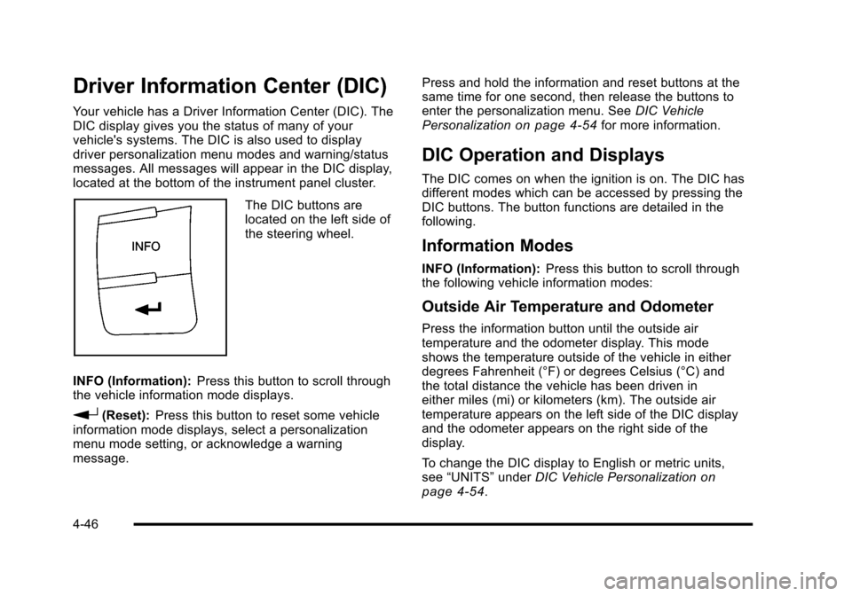
The DIC buttons are
located on the left side of
the steering wheel.
INFO (Information): Press this button to scroll through
the vehicle information mode displays.
r(Reset): Press this button to reset some vehicle
information mode displays, select a personalization
menu mode setting, or acknowledge a warning
message. Press and hold the information and reset buttons at the
same time for one second, then release the buttons to
enter the personalization menu. See
DIC Vehicle
Personalization
on page 4‑54for more information.
DIC Operation and Displays
The DIC comes on when the ignition is on. The DIC has
different modes which can be accessed by pressing the
DIC buttons. The button functions are detailed in the
following.
Information Modes
INFO (Information): Press this button to scroll through
the following vehicle information modes:
Outside Air Temperature and Odometer
Press the information button until the outside air
temperature and the odometer display. This mode
shows the temperature outside of the vehicle in either
degrees Fahrenheit (°F) or degrees Celsius (°C) and
the total distance the vehicle has been driven in
either miles (mi) or kilometers (km). The outside air
temperature appears on the left side of the DIC display
and the odometer appears on the right side of the
display.
To change the DIC display to English or metric units,
see “UNITS” underDIC Vehicle Personalization
on
page 4‑54.
4-46