2010 ASTON MARTIN V8 VANTAGE ignition
[x] Cancel search: ignitionPage 803 of 947

Squeaks and Rattles Repair Manual
July 2010 Page 19 of 21
Figure 6
8. Install the hinge bracket gear onto the new left hinge bracket.
9. Install the new left and right side brackets onto the pane l and torque the screws to 3 Nm (refer to Figure 7).
Figure 7
10. Put the centre-stack instrument panel into position (refer to Figure 8).
Figure 8
11. Connect the electrical connector to ignition start/stop switch (refer to Figure 9).
Page 830 of 947

Electronics Training Programme
Answering Incoming Calls
When receiving an incoming call, the system responds with ‘Call from < Caller ID>’, if available. If
Caller ID is not available:
• The system plays the ‘in-band’ ring tone, if the phone supports it.
• If no ‘in-band’ ring tone is supported , the system generates a local ring tone.
There are two methods of answering an incoming call:
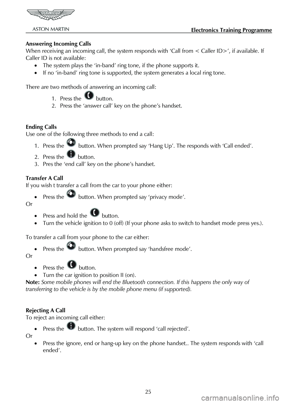
1. Press the button.
2. Press the ‘answer call’ key on the phone’s handset.
Ending Calls
Use one of the following three methods to end a call:
1. Press the button. When prompted say ‘Hang Up’. The responds with ‘Call ended’.
2. Press the button.
3. Pres the ‘end call’ key on the phone’s handset.
Transfer A Call
If you wish t transfer a call from the car to your phone either:
• Press the button. When prompted say ‘privacy mode’.
Or
• Press and hold the button.
• Turn the vehicle ignition to 0 (off) (If your p hone asks to switch to handset mode press yes.).
To transfer a call from your phone to the car either:
• Press the button. When prompted say ‘handsfree mode’.
Or
• Press the button.
• Turn the car ignition to position II (on).
Note: Some mobile phones will end the Bluetooth co nnection. If this happens the only way of
transferring to the vehicle is by the mobile phone menu (if supported).
Rejecting A Call
To reject an incoming call either:
• Press the button. The system will respond ‘call rejected’.
Or
• Press the ignore, end or hang-up key on the phone handset.. The system responds with ‘call
ended’.
25
Page 834 of 947

Electronics Training Programme
The procedure to change the selected language is:
Warning: When changing the system’s language, all contac ts in the Bluetooth contacts list are deleted.
1. Press and hold the button while turning on the vehicle ignition. Continue holding the
button for at least 10 seconds.
The system enters language selection mode and re sponds with ‘Language Menu. Press volume up or
down to change language’.
2. Use the volume Up / Down button to scroll through the language choices. As a language appears, the system plays the prompt for that la nguage (For example: ‘English. To choose this
language, restart the vehicle’.).
When the desired language has been selected, turn t he vehicle ignition to 0 (off). Wait for 6 seconds,
then switch the ignition to II (on), the new language is then loaded.
29
Page 836 of 947

Electronics Training Programme
DIAGNOSTICS
V8 Vantage Connector Pin Allocation
Pin
Number Signal Name Input or
Output Description
3 WAKEUP I Module ignition input from Comfort
Relay via F68
4 MIC (SCRN) I Microphone GND
5 MIC IN+ I Signal input for single-ended
microphone direct from microphone
8 KEYPAD I Input signal from keypad on steering wheel
12 UIM LED O For Active Call LED (amber) – Earth
side switch
13 RADIO MUTE O Mute line to radio (active Low)
14 UIM LED O For Bluetooth Status LED(Blue) – Earth side switch
15 GND I Main Battery Ground
16 GND I Main Battery Ground
23 HF_SPKR + O Audio Output +
24 HF_SPKR + O Audio Output -
31 VPWR I Power supply from Interior Light Relay via F46
32 VPWR I Power supply from Interior Light Relay via F46
31
Page 837 of 947

Electronics Training Programme
DB9 Connector Pin Allocation
Pin
Number Signal Name Input or
Output Description
3 IGN I Module ignition input from Comfort
Relay via F69
4 MIC (SCRN) I Microphone GND or Shield
5 MIC IN+ I Signal input for single-ended or
differential mic.
6 MIC IN- I Signal input for differential microphone
8 KEYPAD I Input signal from keypad on steering
wheel
12 UIM LED O For Active Call LED (amber) – Earth side switch
13 RADIO MUTE O Mute line to radio (active Low)
14 UIM LED O For Bluetooth Status LED(Blue) – Earth side switch
15 GND I Main Battery Ground
16 GND I Main Battery Ground
22 LINEOUT (SCRN) I Audio output screen
25 LINEOUT+ O Audio Output +
26 LINEOUT- O Audio Output -
31 VPWR I Power supply from Interior Light Relay via F46
32 VPWR I Power supply from Interior Light Relay via F46
32
Page 851 of 947

AML EOBD System Operation Summary
Rory O’Curry Aston Martin Lagonda CONFIDENTIAL 1 May 2009
[email protected] AML EOBD Monitors 07 ROC.doc Page 5 of 43
Catalyst Monitor Operation:
DTCs P0420 Bank 1, P0430 Bank 2 for Series System ( and P0420 Complete
System for 'Y pipe' configuration ).
Monitor execution once per driving cycle
Monitor Sequence HO2S monitor complete and OK
Sensors OK ECT, IAT, TP, VSS, CPS
Monitoring Duration Approximately 900 seconds dur ing appropriate conditions (approximately
200 to 600 oxygen sensor switches are collected).
Typical catalyst monitor entry conditions: Minimum Maximum
Time since engine start-up (70 oF start) 240 seconds
Engine Coolant Temp 160 oF 230 oF
Intake Air Temp 20 oF 180 oF
Engine Load 10%
Throttle Position Part Throttle Part Throttle
Time since entering closed loop fuel 30 sec
Vehicle Speed 5 mph 70 mph
Steady Air Mass Flow 1.0 lb/min 5.0 lb/min
( Note: 25 - 35 mph steady state driving must be performed to complete the monitor )
Typical malfunction thresholds:
Rear-to-front O2 sensor switch-ratio/ Index Ratio > 0.75
Catalyst Monitor temporary disablement conditions (other than entry requirements) :
EGR, Secondary air, Front and Rear O2 sensor, Engine Coolant Temperature, Mass Air Flow sensor, Air
Charge Temperature sensor, Profile Ignition Pickup & Throttle Position monitor failure.
Page 871 of 947

AML EOBD System Operation Summary
Rory O’Curry Aston Martin Lagonda CONFIDENTIAL 1 May 2009
[email protected] AML EOBD Monitors 07 ROC.doc Page 25 of 43
VCT Monitor
Variable Cam Timing System Monitor
VCT Hardware
Variable Cam Timing (VCT) enables rotation of the camshaft(s) relative to the crankshaft (phase-shifting)
as a function of engine operating conditions. Intake Only (phase-shifting only the intake cam) is used in
the AML application.
VCT is used primarily to increase internal residua l dilution at part throttle to reduce NOx, and to
improve fuel economy. With Intake Only VCT, the in take camshaft is advanced at part throttle and WOT
(at low to mid-range engine speeds) to open the in take valve earlier for increased residual dilution and
close the intake valve earlier in the compression stroke for increased power. When the engine is cold,
opening the intake valve earlier warms the charge which improves fuel vaporization for less HC
emissions; when the engine is warm, the residua l burned gasses limit peak combustion temperature to
reduce NOx formation.
The VCT system hardware consists of a contro l solenoid and a pulse ring on the camshaft. The PCM
calculates relative cam position using the CMP input to process variable reluctance sensor pulses coming
from the pulse ring mounted on the camshaft. Each pul se wheel has N + 1 teeth where N = the number of
cylinders per bank. The N equally spaced teeth are used for cam phasing; the remaining tooth is used to
determine cylinder # 1 position. Relative cam position is calculated by measuring the time between the
rising edge of profile ignition pickup (PIP ) and the falling edges of the VCT pulses.
VCT Diagnostic
The PCM continually calculates a cam position error value based on the difference between the desired
and actual position and uses this information to cal culate a commanded duty cycle for the VCT solenoid
valve. When energized, engine oil is allowed to flow to the VCT unit thereby advancing and retarding cam
timing. The VCT logic calculates the instantaneous va riance in actual cam position (the squared difference
between actual cam position and commanded cam position), then calculates the long term variance using a
rolling average filter (Exponentially Weighted Moving Average).
If the VCT system is stuck or operates with an consta nt error relative to the target position, the monitor
will detect a variance which will quickly accumulate. There are three variance indices that monitor cam
variance in the retard direction, the advance directi on, and for V engines, the difference between banks. If
any variance index is greater than the malfunction threshold, a VCT target error malfunction will be
indicated (P0011, P0012 Bank 1, P0021, P0022 Bank 2).
The VCT solenoid output driver in the PCM is check ed electrically for open circuit and shorts (P0010
Bank 1, P0020 Bank 2).
VCT Monitor Operation:
Page 873 of 947

AML EOBD System Operation Summary
Rory O’Curry Aston Martin Lagonda CONFIDENTIAL 1 May 2009
[email protected] AML EOBD Monitors 07 ROC.doc Page 27 of 43
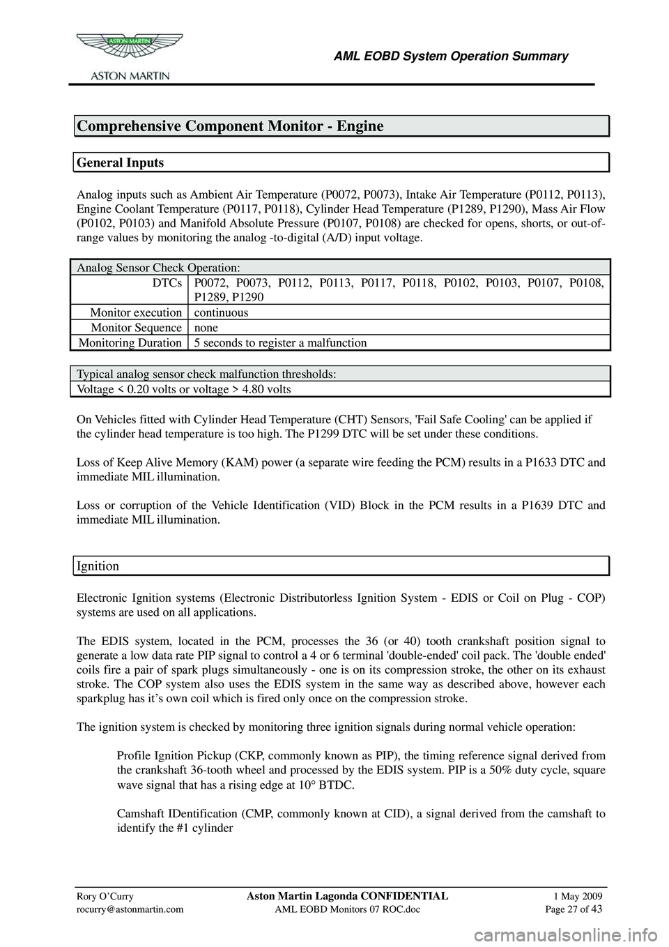
Comprehensive Component Monitor - Engine
General Inputs
Analog inputs such as Ambient Air Temperature (P0072, P0073), Intake Air Temperature (P0112, P0113),
Engine Coolant Temperature (P0117, P0118), Cylinder Head Temperature (P1289, P1290), Mass Air Flow
(P0102, P0103) and Manifold Absolute Pressure (P0107, P0108) are checked for opens, shorts, or out-of-
range values by monitoring the analog -to-digital (A/D) input voltage.
Analog Sensor Check Operation:
DTCs P0072, P0073, P0112, P0113, P0117, P0118, P0102, P0103, P0107, P0108,
P1289, P1290
Monitor execution continuous
Monitor Sequence none
Monitoring Duration 5 seconds to register a malfunction
Typical analog sensor check malfunction thresholds:
Voltage < 0.20 volts or voltage > 4.80 volts
On Vehicles fitted with Cylinder Head Temperature (CHT ) Sensors, 'Fail Safe Cooling' can be applied if
the cylinder head temperature is too high. The P1299 DTC will be set under these conditions.
Loss of Keep Alive Memory (KAM) power (a separate wire feeding the PCM) results in a P1633 DTC and
immediate MIL illumination.
Loss or corruption of the Vehicle Identification (VID) Block in the PCM results in a P1639 DTC and
immediate MIL illumination.
Ignition
Electronic Ignition systems (Electronic Distributorless Ignition System - EDIS or Coil on Plug - COP)
systems are used on all applications.
The EDIS system, located in the PCM, processes the 36 (or 40) tooth crankshaft position signal to
generate a low data rate PIP signal to control a 4 or 6 terminal 'double-ended' coil pack. The 'double ended'
coils fire a pair of spark plugs simultaneously - one is on its compression stroke, the other on its exhaust
stroke. The COP system also uses the EDIS system in the same way as described above, however each
sparkplug has it’s own coil which is fired only once on the compression stroke.
The ignition system is checked by monitoring three ignition signals during normal vehicle operation:
Profile Ignition Pickup (CKP, commonly known as PIP), the timing reference signal derived from the crankshaft 36-tooth wheel and processed by the EDIS system. PIP is a 50% duty cycle, square
wave signal that has a rising edge at 10 ° BTDC.
Camshaft IDentification (CMP, commonly known at CID), a signal derived from the camshaft to identify the #1 cylinder