2010 ASTON MARTIN V8 VANTAGE clutch
[x] Cancel search: clutchPage 879 of 947

AML EOBD System Operation Summary
Rory O’Curry Aston Martin Lagonda CONFIDENTIAL 1 May 2009
[email protected] AML EOBD Monitors 07 ROC.doc Page 33 of 43
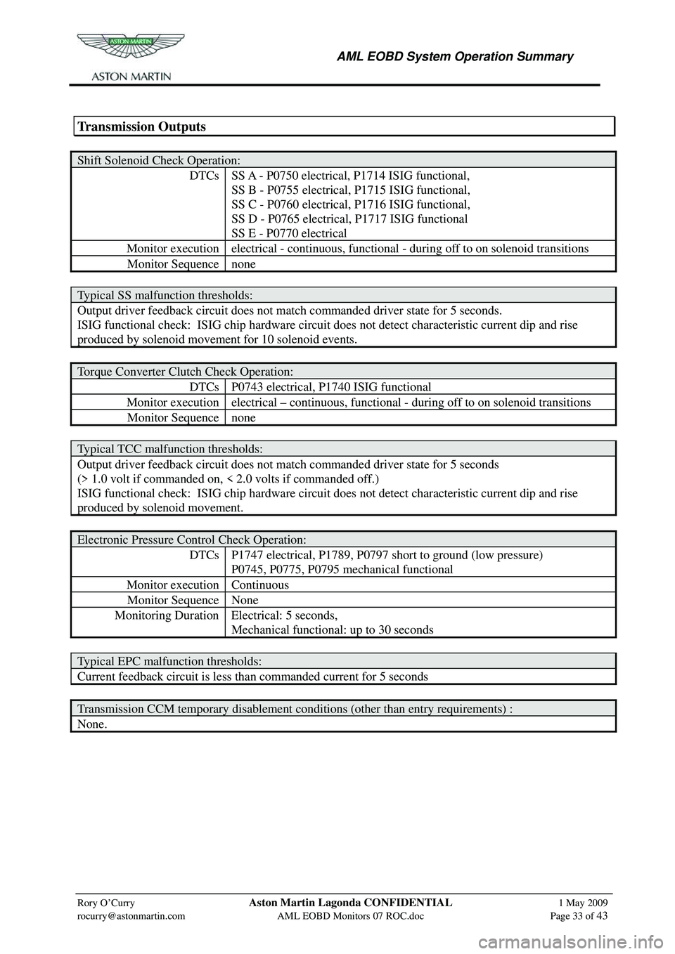
Transmission Outputs
Shift Solenoid Check Operation:
DTCs SS A - P0750 electrical, P1714 ISIG functional,
SS B - P0755 electrical, P1715 ISIG functional,
SS C - P0760 electrical, P1716 ISIG functional,
SS D - P0765 electrical, P1717 ISIG functional
SS E - P0770 electrical
Monitor execution electrical - continuous, functi onal - during off to on solenoid transitions
Monitor Sequence none
Typical SS malfunction thresholds:
Output driver feedback circuit does not match commanded driver state for 5 seconds.
ISIG functional check: ISIG chip hardware circu it does not detect characteristic current dip and rise
produced by solenoid movement for 10 solenoid events.
Torque Converter Clutch Check Operation:
DTCs P0743 electrical, P1740 ISIG functional
Monitor execution electrical – continuous, functi onal - during off to on solenoid transitions
Monitor Sequence none
Typical TCC malfunction thresholds:
Output driver feedback circuit does not match commanded driver state for 5 seconds
(> 1.0 volt if commanded on, < 2.0 volts if commanded off.)
ISIG functional check: ISIG chip hardware circu it does not detect characteristic current dip and rise
produced by solenoid movement.
Electronic Pressure Control Check Operation:
DTCs P1747 electrical, P1789, P0797 short to ground (low pressure)
P0745, P0775, P0795 mechanical functional
Monitor execution Continuous
Monitor Sequence None
Monitoring Duration Electrical: 5 seconds,
Mechanical functional: up to 30 seconds
Typical EPC malfunction thresholds:
Current feedback circuit is less than commanded current for 5 seconds
Transmission CCM temporary disablement conditions (other than entry requirements) :
None.
Page 880 of 947

AML EOBD System Operation Summary
Rory O’Curry Aston Martin Lagonda CONFIDENTIAL 1 May 2009
[email protected] AML EOBD Monitors 07 ROC.doc Page 34 of 43
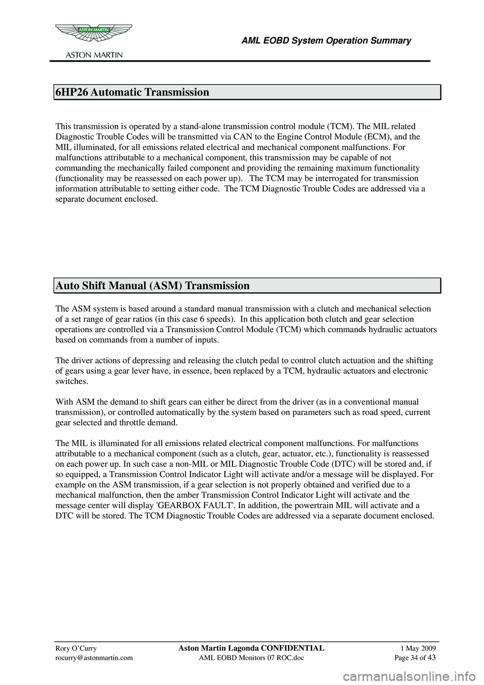
6HP26 Automatic Transmission
This transmission is operated by a stand-alone transmission control module (TCM). The MIL related
Diagnostic Trouble Codes will be transmitted via CAN to the Engine Control Module (ECM), and the
MIL illuminated, for all emissions related electrical and mechanical component malfunctions. For
malfunctions attributable to a mechanical component, this transmission may be capable of not
commanding the mechanically failed component a nd providing the remaining maximum functionality
(functionality may be reassessed on each power up). The TCM may be interrogated for transmission
information attributable to setting either code. The TCM Diagnostic Trouble Codes are addressed via a
separate document enclosed.
Auto Shift Manual (ASM) Transmission
The ASM system is based around a standard manual transmission with a clutch and mechanical selection
of a set range of gear ratios (in this case 6 speeds). In this application both clutch and gear selection
operations are controlled via a Transmission Contro l Module (TCM) which commands hydraulic actuators
based on commands from a number of inputs.
The driver actions of depressing and releasing the clutch pedal to control clutch actuation and the shifting
of gears using a gear lever have, in essence, been re placed by a TCM, hydraulic actuators and electronic
switches.
With ASM the demand to shift gears can either be direct from the driver (as in a conventional manual
transmission), or controlled automatically by the system based on parameters such as road speed, current
gear selected and throttle demand.
The MIL is illuminated for all emissions related electrical component malfunctions. For malfunctions
attributable to a mechanical component (such as a cl utch, gear, actuator, etc.), functionality is reassessed
on each power up. In such case a non-MIL or MIL Diagnos tic Trouble Code (DTC) will be stored and, if
so equipped, a Transmission Control Indicator Light will activate and/or a message will be displayed. For
example on the ASM transmission, if a gear selection is not properly obtained and verified due to a
mechanical malfunction, then the amber Transmission Control Indicator Light will activate and the
message center will display 'GEARBOX FAULT'. In addition, the powertrain MIL will activate and a
DTC will be stored. The TCM Diagnostic Trouble Cod es are addressed via a separate document enclosed.
Page 883 of 947

AML EOBD System Operation Summary
Rory O’Curry Aston Martin Lagonda CONFIDENTIAL 1 May 2009
[email protected] AML EOBD Monitors 07 ROC.doc Page 37 of 43
Glossary of Terms
A/D Analogue to Digital
ASM Auto Shift Manul
BTDC Before Top Dead Centre
CALID CALibration IDentification
CD4E Automatic Transmission for Intermediate size Family saloon.
CID Camshaft Identification.
CKP Crankshaft Position
CMP Camshaft Position
COP Coil on Plug
CPC Camshaft Position Control
CVN Calibration Verification Number
DPFE Delta Pressure Feedback
DTC Diagnostic Trouble Code
ECT Engine Coolant Temperature
EDIS Electronic Distributorless Ignition System
EGR Exhaust Gas Re-circulation.
EOBD European On Bard Diagnostics
EPC Electronic Pressure Control
ETC Electronic Throttle Control
ETM Electronic Throttle Monitor
EVR Electronic Vacuum Regulator
EWMA Exponentially Weighted Moving Average
FMEM Failure Mode and Effects Management
FN Automatic Transmission for Medium size Family Saloon
FWD Front Wheel Drive
HDR High Data Rate
HO2S Heated Oxygen Sensor.
IAC Idle Air Control
IDM Ignition Diagnostic Monitor
IMRC Inlet Manifold Runner Control
IPC Independent Plausibility Checker
KAM Keep Alive Memory
LDR Low Data Rate
LTFT Long Term Fuel Trim
MAF Mass Air Flow
MAP Manifold Absolute Pressure
MIL Malfunction Indicator Lamp
OSS Output Shaft Speed
PCM Powertrain Control Module
PIP Profile Ignition Pickup
RWD Rear Wheel Drive
SAE Society of Automotive Engineers
SAIR Secondary AIR
SCV Swirl Control Valve
STFT Short Term Fuel Trim
TCC Torque Converter Clutch
TCIL Transmission Control Indicator Lamp
TP Throttle Position
TPPC Throttle Plate Position Controller
TRS Transmission Range Sensor
TSS Turbine Shaft Speed
VID Vehicle IDentification
VIN Vehicle Identification No.
VQZ VQuizzer
VMV Vapour Management Valve
Page 905 of 947

Aston Martin V8 Vantage2009MY OBDII Documentation 4.7L Aston Martin Confidential
Component P CodesMalfunction Strategy
Description Malfunction Criteria
(Fault) Fault condition
(Internal labels) Threshold Value
(Fault condition) Entry conditions Entry conditions values Filter Time to
log DTC
Gear Position sensor P0916 Gear Position sensor
short to GND Gear Position signal low Output Voltage < th_low th_low = 0,5V (Key ON) AND NOT
(cranking) AND
VSupply inside prope
r VSupply range = 7V-24.5V 500ms
Gear Position sensor P0917 Gear Position sensor
short to battery or open circuit Gear position signal high Output Voltage > th_high
th_high = 4,5V (Key ON) AND NOT
(cranking) AND
VSupply inside proper VSupply range = 7V-24.5V 500ms
Gear Position sensor P0915 Mechanical damage o
f
magnet holder;
Electrical offset.
Internal sensor failure Gear position signal wrong value The calculated gear from the gear
and shift position sensors is different than the last engaged gear(See annexed Chart 1) th = 3% (Key ON) AND NOT
(cranking) AND
VSupply inside prope
r
range VSupply range = 7V-24.5V 500ms
Shift position P0907 Gear Position sensor short to battery or open circuit Shift position signal high Output Voltage > th_high
th_high = 4,5V (Key ON) AND NOT
(cranking) AND
VSupply inside proper VSupply range = 7V-24.5V 500ms
Shift position P0906 Gear Position sensor short to GNDShift position signal low
Output Voltage < th_low th_low = 0,5V (Key ON) AND NOT
(cranking) AND
VSupply inside proper VSupply range = 7V-24.5V 500ms
Shift position P0905 Mechanical damage o
f
magnet holder;
Electrical offset.
Internal sensor failure Shift position signal wrong value The shift position signal is not
coherent with the self tuned value fo
r
at least one gear.ShiftPosition (i) -
ShiftPositionSelfTuned (i) > th for a timeout
where i=1,2,…,7 th = 50 bit
timeout = 3s (Key ON) AND NOT
(cranking) AND
VSupply inside prope
r
range VSupply range = 7V-24.5V 500ms
Clutch position sensor P0807 P1/ P2 wire short
circuit to GND Clutch position sensor - Primary
Circuit low The asic UH05 inside the TCU
detects the fault and communicate it to the uP
Output Voltage < th_low th_low = 0,5V (Key ON) AND NOT
(cranking) AND
VSupply inside proper
range VSupply range = 7V-24.5V 50ms
Clutch position sensor P0808 P1/ P2 wire short
circuit to battery or open circuit Clutch position sensor - Primary
Circuit high The asic UH05 inside the TCU
detects the fault and communicate it to the uP
Output Voltage > th_high th_high = 4,5V (Key ON) AND NOT
(cranking) AND
VSupply inside proper
range VSupply range = 7V-24.5V 50ms
Clutch position sensor P173A S1/ S2 wire short
circuit to GND Clutch position sensor -
Secondary Circuit low The asic UH05 inside the TCU
detects the fault and communicate it to the uP
Output Voltage < th_low th_low = 0,5V (Key ON) AND NOT
(cranking) AND
VSupply inside proper
range VSupply range = 7V-24.5V 50ms
ASM OBD
128/04/2008
Page 906 of 947

Aston Martin V8 Vantage2009MY OBDII Documentation 4.7L Aston Martin Confidential
Component P CodesMalfunction Strategy
Description Malfunction Criteria
(Fault) Fault condition
(Internal labels) Threshold Value
(Fault condition) Entry conditions Entry conditions values Filter Time to
log DTCClutch position sensor P173B S1/ S2 wire short
circuit to battery or open circuit Clutch position sensor -
Secondary Circuit high The asic UH05 inside the TCU
detects the fault and communicate it to the uP
Output Voltage > th_high th_high = 4,5V (Key ON) AND NOT
(cranking) AND
VSupply inside prope
r
range VSupply range = 7V-24.5V 50ms
Clutch position sensor P0805 Short circuit between
P1 and P2 or short
circuit between S1 and S2 Clutch position sensor - Primary
Secondary short circuit The clutch position signal is a fixed
value (around 2.5 V)
See annexed Chart 2 th_1= 5 km/h
th_2= 2000 bit
timeout_1=100ms timeout_2=50ms (Key ON) AND NOT
(cranking) AND
VSupply inside proper
range VSupply range = 7V-24.5V 50ms
Hydraulic
pressure sensor P0935 Hydraulic pressure
sensor short to GND or open circuit Hydraulic pressure signal circuit
high Output Voltage < th_low th_low = 0,39V (Key ON) AND NOT
(cranking) AND
VSupply inside proper VSupply range = 7V-24.5V 500ms
Hydraulic
pressure sensor P0934 Hydraulic pressure
sensor short to battery Hydraulic pressure signal circuit
low Output Voltage > th_high th_high = 4,79V (Key ON) AND NOT
(cranking) AND
VSupply inside proper VSupply range = 7V-24.5V 500ms
Hydraulic
pressure sensor P0932 Internal Sensor
Damage or open
circuit on the ground sensor wire Hydraulic pressure signal wrong
value Wrong constant pressure value
detected through a correlation
between the pressure variation and an estimation of the oil flow (Key ON) AND NOT
(cranking) AND
VSupply inside proper
range VSupply range = 7V-24.5V 500ms
Kl.30 Power Supply P1794 Open circuit or broken
fuse on TCU supply Kl.30 Power Supply open circuit Power Supply < V_th
V_th = 3V (Key ON) AND NOT
(cranking) 500ms
External sensors power supply or sensor ground P0641 Failure of the sensor
power voltage supply External sensors power supply
or sensor ground open circuit or short circuit V_Sensor_Supply inside proper
range V_Sensor_Supply range
= 4V-5V (Key ON) AND NOT
(cranking) AND
VSupply inside proper
range VSupply range = 7V-24.5V 2500ms
Engine speed from CAN U0401 Internal Problem on
Engine Control System Engine ECU: Engine speed fro
m
CAN. Signal not valid
CAN engine sp = inv_th inv_th = FFFFh NOT (Cranking) AND
(ECU ON since t_on)t_on = 200 ms 1000ms
Engine speed from CAN U1900 Internal Problem on
Engine Control System Engine ECU: Engine speed fro
m
CAN. Signal absent (wrong zero
rpm signal) (CAN engine sp = 0) AND (Engine
ON) Engine ON 1000ms
Engine speed from CAN U1920 Internal Problem on
Engine Control System Engine ECU: Engine speed fro
m
CAN. Signal wrong
(CAN engine speed different form
Clutch speed) AND (CAN engine
speed different from Driveline speed x gear ratio) Seed tollerance=
500rpm (Engine ON) AND
(clutch closed) AND (gear engaged) 1000ms
ASM OBD
228/04/2008
Page 907 of 947

Aston Martin V8 Vantage2009MY OBDII Documentation 4.7L Aston Martin Confidential
Component P CodesMalfunction Strategy
Description Malfunction Criteria
(Fault) Fault condition
(Internal labels) Threshold Value
(Fault condition) Entry conditions Entry conditions values Filter Time to
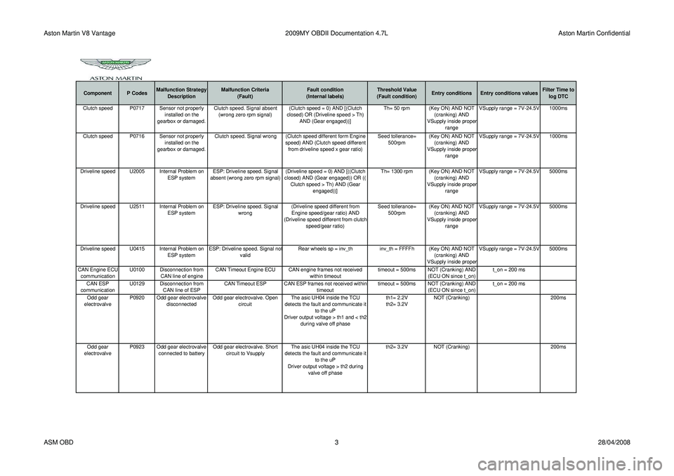
log DTCClutch speed P0717 Sensor not properly installed on the
gearbox or damaged. Clutch speed. Signal absent
(wrong zero rpm signal) (Clutch speed = 0) AND [(Clutch
closed) OR (Driveline speed > Th) AND (Gear engaged))] Th= 50 rpm (Key ON) AND NOT
(cranking) AND
VSupply inside prope
r
range VSupply range = 7V-24.5V 1000ms
Clutch speed P0716 Sensor not properly installed on the
gearbox or damaged. Clutch speed. Signal wrong (Clutch speed different form Engine
speed) AND (Clutch speed different from driveline speed x gear ratio) Seed tollerance=
500rpm (Key ON) AND NOT
(cranking) AND
VSupply inside proper
range VSupply range = 7V-24.5V 1000ms
Driveline speed U2005 Internal Problem on ESP systemESP: Driveline speed. Signal
absent (wrong zero rpm signal) (Driveline speed = 0) AND [((Clutch
closed) AND (Gear engaged)) OR (( Clutch speed > Th) AND (Gear engaged))] Th= 1300 rpm (Key ON) AND NOT
(cranking) AND
VSupply inside proper
range VSupply range = 7V-24.5V 5000ms
Driveline speed U2511 Internal Problem on ESP systemESP: Driveline speed. Signal
wrong (Driveline speed different from
Engine speed/gear ratio) AND
(Driveline speed different from clutch speed/gear ratio) Seed tollerance=
500rpm (Key ON) AND NOT
(cranking) AND
VSupply inside proper
range VSupply range = 7V-24.5V 5000ms
Driveline speed U0415 Internal Problem on ESP systemESP: Driveline speed. Signal no
t
valid Rear wheels sp = inv_th
inv_th = FFFFh (Key ON) AND NOT
(cranking) AND
VSupply inside prope
r VSupply range = 7V-24.5V 5000ms
CAN Engine ECU communication U0100 Disconnection from
CAN line of engine CAN Timeout Engine ECU CAN engine frames not received
within timeouttimeout = 500ms NOT (Cranking) AND
(ECU ON since t_on) t_on = 200 ms
CAN ESP
communication U0129 Disconnection from
CAN line of ESP CAN Timeout ESP CAN ESP frames not received within
timeouttimeout = 500ms NOT (Cranking) AND
(ECU ON since t_on) t_on = 200 ms
Odd gear
electrovalve P0920 Odd gear electrovalve
disconnected Odd gear electrovalve. Open
circuit The asic UH04 inside the TCU
detects the fault and communicate it to the uP
Driver output voltage > th1 and < th2 during valve off phase th1= 2.2V
th2= 3.2V
NOT (Cranking)
200ms
Odd gear
electrovalve P0923 Odd gear electrovalve
connected to battery Odd gear electrovalve. Short
circuit to Vsupply The asic UH04 inside the TCU
detects the fault and communicate it to the uP
Driver output voltage > th2 during valve off phase th2= 3.2V
NOT (Cranking) 200ms
ASM OBD 328/04/2008
Page 908 of 947

Aston Martin V8 Vantage2009MY OBDII Documentation 4.7L Aston Martin Confidential
Component P CodesMalfunction Strategy
Description Malfunction Criteria
(Fault) Fault condition
(Internal labels) Threshold Value
(Fault condition) Entry conditions Entry conditions values Filter Time to
log DTCOdd gear
electrovalve P0922 Odd gear electrovalve
connected to GND Odd gear electrovalve. Short
circuit to GND The asic UH04 inside the TCU
detects the fault and communicate it to the uP
Driver output current > th3 during valve on phase th3= 3.7A
NOT (Cranking) 200ms
Even gear
electrovalve P0924 Even gear
electrovalve
disconnected Even gear electrovalve. Open
circuit The asic UH04 inside the TCU
detects the fault and communicate it to the uP
Driver output voltage > th1 and < th2 during valve off phase th1= 2.2V
th2= 3.2V
NOT (Cranking)
200ms
Even gear
electrovalve P0927
Even gear
electrovalve
connected to battery Even gear electrovalve. Short
circuit to Vsupply The asic UH04 inside the TCU
detects the fault and communicate it to the uP
Driver output voltage > th2 during valve off phase th2= 3.2V
NOT (Cranking) 200ms
Even gear
electrovalve P0926 Even gear
electrovalve
connected to GND Even gear electrovalve. Short
circuit to GND The asic UH04 inside the TCU
detects the fault and communicate it to the uP
Driver output current > th3 during valve on phase th3= 3.7A
NOT (Cranking) 200ms
Clutch
electrovalve P0900 Clutch electrovalve
disconnected Clutch electrovalve. Open circuit The asic UH04 inside the TCU
detects the fault and communicate it to the uP
Driver output voltage > th1 and < th2 during valve off phase th1= 2.2V
th2= 3.2V
NOT (Cranking)
200ms
Clutch
electrovalve P0903 Clutch electrovalve
connected to battery Clutch electrovalve. Short circuit
to Vsupply The asic UH04 inside the TCU
detects the fault and communicate it to the uP
Driver output voltage > th2 during valve off phase th2= 3.2V
NOT (Cranking) 200ms
ASM OBD 428/04/2008
Page 909 of 947

Aston Martin V8 Vantage2009MY OBDII Documentation 4.7L Aston Martin Confidential
Component P CodesMalfunction Strategy
Description Malfunction Criteria
(Fault) Fault condition
(Internal labels) Threshold Value
(Fault condition) Entry conditions Entry conditions values Filter Time to
log DTCClutch
electrovalve P0902 Clutch electrovalve
connected to GND Clutch electrovalve. Short circuit
to GND The asic UH04 inside the TCU
detects the fault and communicate it to the uP
Driver output current > th3 during valve on phase th3= 3.7A
NOT (Cranking) 200ms
Shift brake
electrovalve. Open circuit P0928 Shift brake
electrovalve
disconnected Shift brake electrovalve. Open
circuit The asic UH04 inside the TCU
detects the fault and communicate it to the uP
Driver output voltage > th1 and < th2 during valve off phase th1= 2.2V
th2= 3.2V
NOT (Cranking)
200ms
Shift brake
electrovalve P0931 Shift brake
electrovalve
connected to battery Shift brake electrovalve. Short
circuit to Vsupply The asic UH04 inside the TCU
detects the fault and communicate it to the uP
Driver output voltage > th2 during valve off phase th2= 3.2V
NOT (Cranking) 200ms
Shift brake
electrovalve P0930 Shift brake
electrovalve
connected GND Shift brake electrovalve. Short
circuit to GND The asic UH04 inside the TCU
detects the fault and communicate it to the uP
Driver output current > th3 during valve on phase th3= 3.7A
NOT (Cranking) 200ms
Pump relay P0945 Pump relay disconnectedPump relay Open circuit The asic UH04 inside the TCU
detects the fault and communicate it to the uP
Driver output voltage > th1 and < th2 during valve off phase th1= 2.2V
th2= 3.2V
NOT (Cranking)
200ms
Pump relay P0948 Pump relay connected to batteryPump relay Short circuit to
Vsupply The asic UH04 inside the TCU
detects the fault and communicate it to the uP
Driver output voltage > th2 during valve off phase th2= 3.2V
NOT (Cranking) 200ms
ASM OBD 528/04/2008