2010 ASTON MARTIN V8 VANTAGE manual transmission
[x] Cancel search: manual transmissionPage 797 of 947

Squeaks and Rattles Repair Manual
July 2010 Page 13 of 21
Sat-Nav Chatter
SRO: 19.07.CG
Safe VINs: DBS - E01840, DB9 - A12676, V8 Vantage - C13743
Repair:
Pre safe VIN
CAUTION:
BE CAREFUL WHEN YOU RELEASE THE INSTRUMENT PANEL VENEER BEZEL. THE SURFACE FINISH CAN BE EASILY DAMAGED.
1. Release the four clips that attach the centre-s tack instrument panel (refer to Figure 1).
Figure 1
2. Disconnect the electrical connectors from each of the fo ur transmission control switches (refer to Figure 2).
Figure 2
3. Disconnect the electrical connector from the igni tion start/stop switch (refer to Figure 3).
Page 799 of 947

Squeaks and Rattles Repair Manual
July 2010 Page 15 of 21
Figure 6
9. Install the sat-nav top panel.
10. Put the instrument panel into po sition (refer to Figure 7).
Figure 7
11. Connect the electrical connector to ignition start/stop switch (refer to Figure 8).
Figure 8
12. Connect the electrical connectors to each of the four transmission control switches (refer to Figure 9).
Page 801 of 947

Squeaks and Rattles Repair Manual
July 2010 Page 17 of 21
Sat-Nav Rattle (Loose in the aperture)
SRO: 19.07.CJ
Safe VINs: DBS - E01610, DB9 - A12546, V8 Vantage - C13503, V12 Vantage - S00185
Repair
CAUTION:
BE CAREFUL WHEN YOU RELEASE THE INSTRUMENT PANEL VENEER BEZEL. THE SURFACE FINISH CAN BE EASILY DAMAGED.
1. Release the four clips that attach the centre-s tack instrument panel (refer to Figure 1).
Figure 1
2. Disconnect the electrical connectors from each of the fo ur transmission control switches (refer to Figure 2).
Figure 2
3. Disconnect the electrical connector from the igni tion start/stop switch (refer to Figure 3).
Page 804 of 947

Squeaks and Rattles Repair Manual
Page 20 of 21 Issue 3
Figure 9
12. Connect the electrical connectors to each of the four transmission control switches (refer to Figure 10).
Figure 10
13. Make sure that the heater vents are correctly aligned.
14. Push the centre-stack instrument panel until it engages with the four retaining clips.
Page 848 of 947

AML EOBD System Operation Summary
Rory O’Curry Aston Martin Lagonda CONFIDENTIAL 1 May 2009
[email protected] AML EOBD Monitors 07 ROC.doc Page 2 of 43
AML EOBD System Operation
Summary for Gasoline Engines.
Contents
Introduction ........................................................................................................................................................................................3
Catalyst Efficiency Monitor ...............................................................................................................................................................4
Misfire Monitor..................................................................................................................................................................................6
Fuel System Monitor ..........................................................................................................................................................................9
HO2S Monitor............................................................................................................................... ...................................................10
Differential Pressure Feedback EGR System Monitor.....................................................................................................................13
Electronic Throttle Monitor............................................................................................................................... ...............................16
Dual MAF Diagnostic............................................................................................................................... .......................................18
SAIR Monitor............................................................................................................................... ....................................................22
VCT Monitor............................................................................................................................... .....................................................25
Comprehensive Component Monitor - Engine............................................................................................................................... ..27
Comprehensive Component Monitor - Manual Transmission..........................................................................................................30
Comprehensive Component Monitor - Automatic Transmission .....................................................................................................31
6HP26 Automatic Transmission............................................................................................................................... ........................34
Auto Shift Manual (ASM) Transmission............................................................................................................................... ...........34
Inspection Maintenance Readiness Code............................................................................................................................... ..........35
Tamper Protection............................................................................................................................... .............................................35
Serial Data Link Connector............................................................................................................................... ...............................35
Serial Data Link Communication Protocol............................................................................................................................... ........35
Serial Data Link MIL Illumination............................................................................................................................... ....................36
Glossary of Terms............................................................................................................................... .............................................37
MIL Code List............................................................................................................................... ...................................................39
MIL Symbol............................................................................................................................... ......................................................43
Page 876 of 947

AML EOBD System Operation Summary
Rory O’Curry Aston Martin Lagonda CONFIDENTIAL 1 May 2009
[email protected] AML EOBD Monitors 07 ROC.doc Page 30 of 43
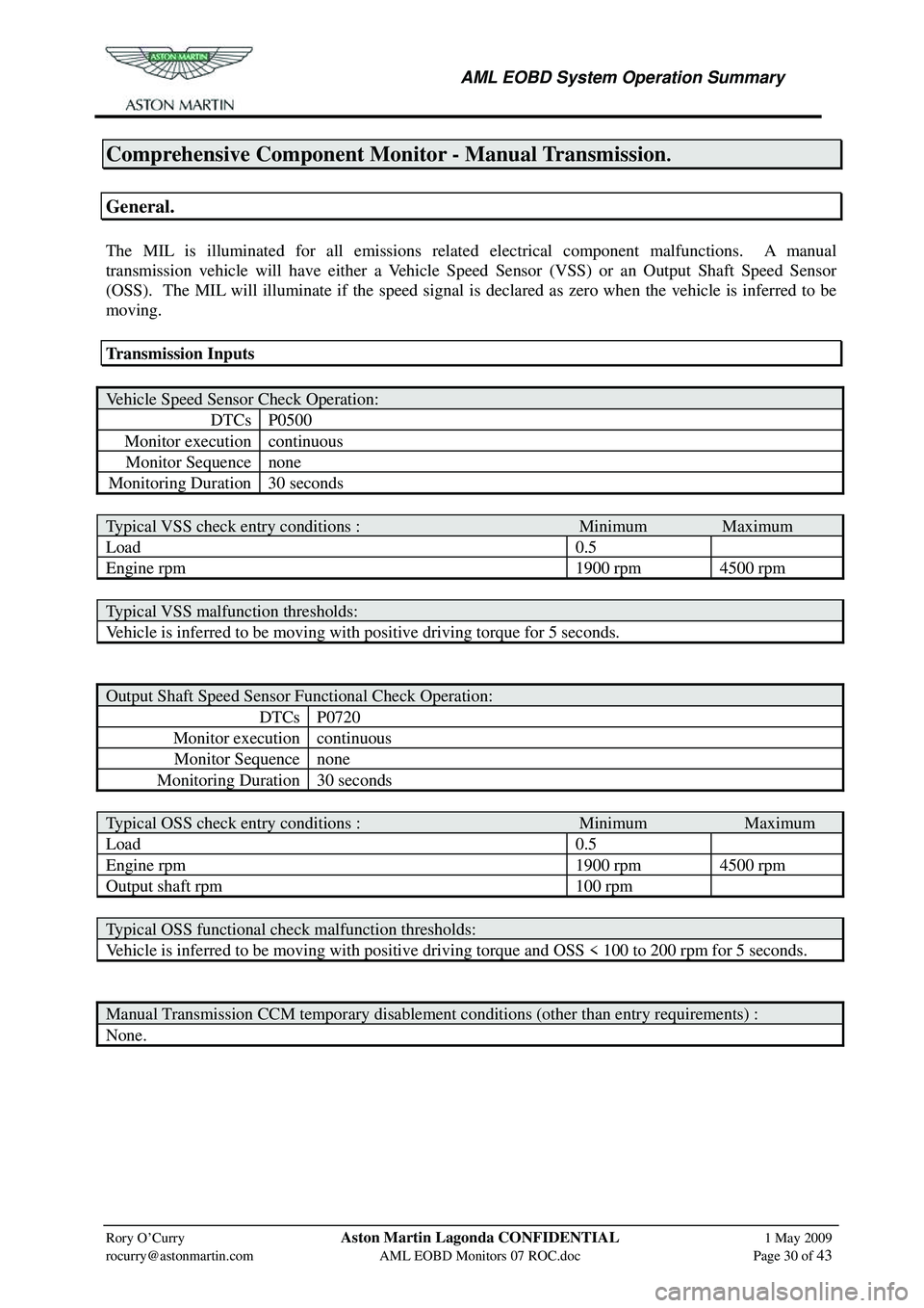
Comprehensive Component Monitor - Manual Transmission.
General.
The MIL is illuminated for all emissions relate d electrical component malfunctions. A manual
transmission vehicle will have either a Vehicle Speed Sensor (VSS) or an Output Shaft Speed Sensor
(OSS). The MIL will illuminate if the speed signal is declared as zero when the vehicle is inferred to be
moving.
Transmission Inputs
Vehicle Speed Sensor Check Operation:
DTCs P0500
Monitor execution continuous
Monitor Sequence none
Monitoring Duration 30 seconds
Typical VSS check entry conditions : Minimum Maximum
Load 0.5
Engine rpm 1900 rpm 4500 rpm
Typical VSS malfunction thresholds:
Vehicle is inferred to be moving with positive driving torque for 5 seconds.
Output Shaft Speed Sensor Functional Check Operation:
DTCs P0720
Monitor execution continuous
Monitor Sequence none
Monitoring Duration 30 seconds
Typical OSS check entry conditions : Minimum Maximum
Load 0.5
Engine rpm 1900 rpm 4500 rpm
Output shaft rpm 100 rpm
Typical OSS functional check malfunction thresholds:
Vehicle is inferred to be moving with positive driving torque and OSS < 100 to 200 rpm for 5 seconds.
Manual Transmission CCM temporary disablement conditions (other than entry requirements) :
None.
Page 880 of 947

AML EOBD System Operation Summary
Rory O’Curry Aston Martin Lagonda CONFIDENTIAL 1 May 2009
[email protected] AML EOBD Monitors 07 ROC.doc Page 34 of 43
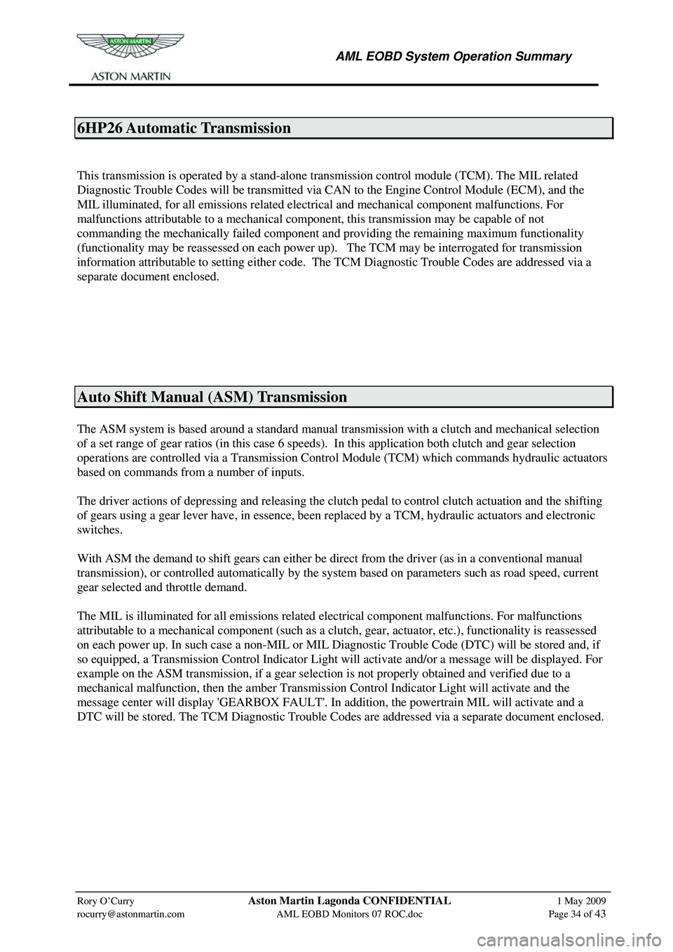
6HP26 Automatic Transmission
This transmission is operated by a stand-alone transmission control module (TCM). The MIL related
Diagnostic Trouble Codes will be transmitted via CAN to the Engine Control Module (ECM), and the
MIL illuminated, for all emissions related electrical and mechanical component malfunctions. For
malfunctions attributable to a mechanical component, this transmission may be capable of not
commanding the mechanically failed component a nd providing the remaining maximum functionality
(functionality may be reassessed on each power up). The TCM may be interrogated for transmission
information attributable to setting either code. The TCM Diagnostic Trouble Codes are addressed via a
separate document enclosed.
Auto Shift Manual (ASM) Transmission
The ASM system is based around a standard manual transmission with a clutch and mechanical selection
of a set range of gear ratios (in this case 6 speeds). In this application both clutch and gear selection
operations are controlled via a Transmission Contro l Module (TCM) which commands hydraulic actuators
based on commands from a number of inputs.
The driver actions of depressing and releasing the clutch pedal to control clutch actuation and the shifting
of gears using a gear lever have, in essence, been re placed by a TCM, hydraulic actuators and electronic
switches.
With ASM the demand to shift gears can either be direct from the driver (as in a conventional manual
transmission), or controlled automatically by the system based on parameters such as road speed, current
gear selected and throttle demand.
The MIL is illuminated for all emissions related electrical component malfunctions. For malfunctions
attributable to a mechanical component (such as a cl utch, gear, actuator, etc.), functionality is reassessed
on each power up. In such case a non-MIL or MIL Diagnos tic Trouble Code (DTC) will be stored and, if
so equipped, a Transmission Control Indicator Light will activate and/or a message will be displayed. For
example on the ASM transmission, if a gear selection is not properly obtained and verified due to a
mechanical malfunction, then the amber Transmission Control Indicator Light will activate and the
message center will display 'GEARBOX FAULT'. In addition, the powertrain MIL will activate and a
DTC will be stored. The TCM Diagnostic Trouble Cod es are addressed via a separate document enclosed.