2009 YAMAHA YZ450F wheel bolt torque
[x] Cancel search: wheel bolt torquePage 21 of 190

1-11
TORQUE-CHECK POINTS
TORQUE-CHECK POINTS
Concerning the tightening torque, refer to "TIGHTENING TORQUES" section in the CHAPTER 2.
Frame construction Frame to rear frame
Combined seat and fuel tank Fuel tank to frame
Exhaust system Silencer to rear frame
Engine mounting Frame to engine
Engine bracket to engine
Engine bracket to frame
Steering Steering stem to handlebar Steering stem to frame
Steering stem to upper bracket
Upper bracket to handlebar
Suspension Front Steering stem to front fork Front fork to upper bracket
Front fork to lower bracket
Rear For link type Assembly of links
Link to frame
Link to rear shock absorber
Link to swingarm
Installation of rear shock absorber Rear shock absorber to frame
Installation of swingarm Tightening of pivot shaft
Wheel Installation of wheel Front Tightening of wheel axle
Tightening of axle holder
Rear Tightening of wheel axle
Wheel to rear wheel sprocket
Brake Front Brake caliper to front fork
Brake disc to wheel
Tightening of union bolt
Brake master cylinder to handlebar
Tightening of bleed screw
Tightening of brake hose holder
Rear Brake pedal to frame
Brake disc to wheel
Tightening of union bolt
Brake master cylinder to frame
Tightening of bleed screw
Tightening of brake hose holder
Fuel system Fuel tank to fuel cock
Lubrication system Tightening of oil hose clamp
Page 33 of 190

2-11
TIGHTENING TORQUES
Exhaust pipe protector M6 × 1.0 3 10 1.0 7.2
Carburetor joint M6 × 1.0 3 10 1.0 7.2
Carburetor joint clamp M4 × 0.7 1 3 0.3 2.2
△Air filter case M6 × 1.0 2 8 0.8 5.8
Air filter joint clamp M6 × 1.0 1 3 0.3 2.2
Air filter joint and air filter case M5 × 0.8 1 4 0.4 2.9
Throttle cable adjust bolt and locknut M6 × 0.75 1 4 0.4 2.9
Throttle cable (pull) M6 × 1.0 1 4 0.4 2.9
Throttle cable (return) M12 × 1.0 1 11 1.1 8.0
Throttle cable cover M5 × 0.8 2 4 0.4 2.9
Hot starter plunger M12 × 1.0 1 2 0.2 1.4
Hot starter cable adjust bolt and locknut M6 × 0.75 1 4 0.4 2.9
Air filter element M6 × 1.0 1 2 0.2 1.4
Radiator stay M6 × 1.0 6 7 0.7 5.1
Radiator M6 × 1.0 4 10 1.0 7.2
Radiator hose clamp M6 × 1.0 8 2 0.2 1.4
Radiator pipe 1, 2 M6 × 1.0 2 10 1.0 7.2
Impeller M8 × 1.25 1 14 1.4 10
Water pump housing cover M6 × 1.0 3 10 1.0 7.2
Coolant drain bolt M6 × 1.0 1 10 1.0 7.2
Oil pump cover M4 × 0.7 1 2 0.2 1.4
Oil pump M6 × 1.0 2 10 1.0 7.2
Oil pump drive gear shaft M6 × 1.0 1 10 1.0 7.2
Oil filter element drain bolt M6 × 1.0 1 10 1.0 7.2
Oil filter element cover M6 × 1.0 2 10 1.0 7.2
Oil pressure check bolt M6 × 1.0 1 10 1.0 7.2
△Oil hose clamp — 2 2 0.2 1.4
Crankshaft end accessing screw M27 × 1.5 1 10 1.0 7.2
Timing mark accessing screw M14 × 1.5 1 6 0.6 4.3
Clutch cover M6 × 1.0 7 10 1.0 7.2
Right crankcase cover M6 × 1.0 8 10 1.0 7.2
Right crankcase cover M6 × 1.0 2 12 1.2 8.7
Left crankcase cover M6 × 1.0 8 10 1.0 7.2
Crankcase M6 × 1.0 12 12 1.2 8.7
Clutch cable holder M6 × 1.0 2 10 1.0 7.2
Oil drain bolt (right crankcase) M10 × 1.25 1 20 2.0 14
Oil drain bolt (left crankcase) M8 × 1.25 1 20 2.0 14
Oil check bolt (crankcase) M6 × 1.0 1 10 1.0 7.2
Oil strainer M6 × 1.0 1 10 1.0 7.2
Crankcase bearing stopper M6 × 1.0 8 10 1.0 7.2
Crankcase bearing stopper (crankshaft) M6 × 1.0 4 14 1.4 10
Drive axle oil seal stopper M6 × 1.0 2 10 1.0 7.2
Kick shaft ratchet wheel guide M6 × 1.0 2 12 1.2 8.7
Kickstarter crank M8 × 1.25 1 33 3.3 24Part to be tightened Thread size Q'tyTightening torque
Nm m•kg ft•lb
Page 35 of 190

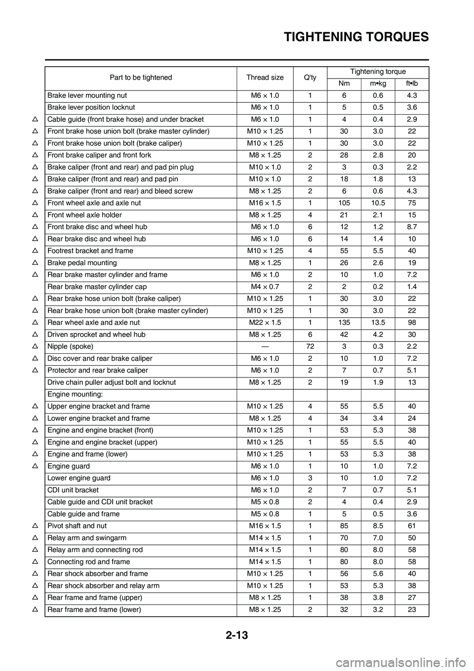
2-13
TIGHTENING TORQUES
Brake lever mounting nut M6 × 1.0 1 6 0.6 4.3
Brake lever position locknut M6 × 1.0 1 5 0.5 3.6
△Cable guide (front brake hose) and under bracket M6 × 1.0 1 4 0.4 2.9
△Front brake hose union bolt (brake master cylinder) M10 × 1.25 1 30 3.0 22
△Front brake hose union bolt (brake caliper) M10 × 1.25 1 30 3.0 22
△Front brake caliper and front fork M8 × 1.25 2 28 2.8 20
△Brake caliper (front and rear) and pad pin plug M10 × 1.0 2 3 0.3 2.2
△Brake caliper (front and rear) and pad pin M10 × 1.0 2 18 1.8 13
△Brake caliper (front and rear) and bleed screw M8 × 1.25 2 6 0.6 4.3
△Front wheel axle and axle nut M16 × 1.5 1 105 10.5 75
△Front wheel axle holder M8 × 1.25 4 21 2.1 15
△Front brake disc and wheel hub M6 × 1.0 6 12 1.2 8.7
△Rear brake disc and wheel hub M6 × 1.0 6 14 1.4 10
△Footrest bracket and frame M10 × 1.25 4 55 5.5 40
△Brake pedal mounting M8 × 1.25 1 26 2.6 19
△Rear brake master cylinder and frame M6 × 1.0 2 10 1.0 7.2
Rear brake master cylinder cap M4 × 0.7 2 2 0.2 1.4
△Rear brake hose union bolt (brake caliper) M10 × 1.25 1 30 3.0 22
△Rear brake hose union bolt (brake master cylinder) M10 × 1.25 1 30 3.0 22
△Rear wheel axle and axle nut M22 × 1.5 1 135 13.5 98
△Driven sprocket and wheel hub M8 × 1.25 6 42 4.2 30
△Nipple (spoke) — 72 3 0.3 2.2
△Disc cover and rear brake caliper M6 × 1.0 2 10 1.0 7.2
△Protector and rear brake caliper M6 × 1.0 2 7 0.7 5.1
Drive chain puller adjust bolt and locknut M8 × 1.25 2 19 1.9 13
Engine mounting:
△Upper engine bracket and frame M10 × 1.25 4 55 5.5 40
△Lower engine bracket and frame M8 × 1.25 4 34 3.4 24
△Engine and engine bracket (front) M10 × 1.25 1 53 5.3 38
△Engine and engine bracket (upper) M10 × 1.25 1 55 5.5 40
△Engine and frame (lower) M10 × 1.25 1 53 5.3 38
△Engine guard M6 × 1.0 1 10 1.0 7.2
Lower engine guard M6 × 1.0 3 10 1.0 7.2
CDI unit bracket M6 × 1.0 2 7 0.7 5.1
Cable guide and CDI unit bracket M5 × 0.8 2 4 0.4 2.9
Cable guide and frame M5 × 0.8 1 5 0.5 3.6
△Pivot shaft and nut M16 × 1.5 1 85 8.5 61
△Relay arm and swingarm M14 × 1.5 1 70 7.0 50
△Relay arm and connecting rod M14 × 1.5 1 80 8.0 58
△Connecting rod and frame M14 × 1.5 1 80 8.0 58
△Rear shock absorber and frame M10 × 1.25 1 56 5.6 40
△Rear shock absorber and relay arm M10 × 1.25 1 53 5.3 38
△Rear frame and frame (upper) M8 × 1.25 1 38 3.8 27
△Rear frame and frame (lower) M8 × 1.25 2 32 3.2 23Part to be tightened Thread size Q'tyTightening torque
Nm m•kg ft•lb
Page 67 of 190

3-21
CHASSIS
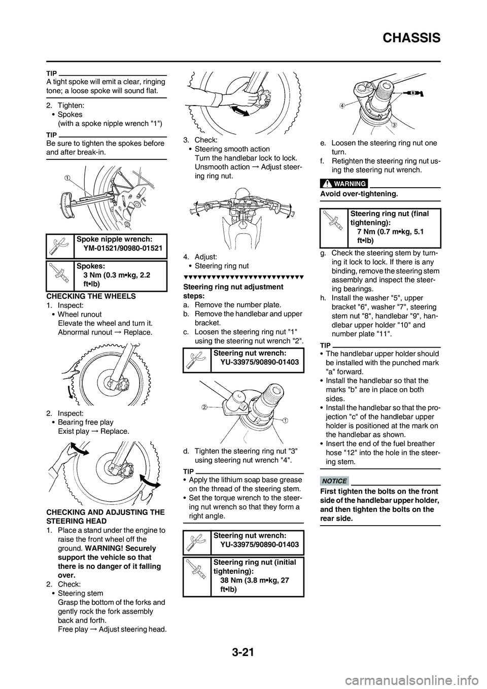
A tight spoke will emit a clear, ringing
tone; a loose spoke will sound flat.
2. Tighten:
• Spokes
(with a spoke nipple wrench "1")
Be sure to tighten the spokes before
and after break-in.
CHECKING THE WHEELS
1. Inspect:
• Wheel runout
Elevate the wheel and turn it.
Abnormal runout→ Replace.
2. Inspect:
• Bearing free play
Exist play→Replace.
CHECKING AND ADJUSTING THE
STEERING HEAD
1. Place a stand under the engine to
raise the front wheel off the
ground. WARNING! Securely
support the vehicle so that
there is no danger of it falling
over.
2. Check:
• Steering stem
Grasp the bottom of the forks and
gently rock the fork assembly
back and forth.
Free play→Adjust steering head.3. Check:
• Steering smooth action
Turn the handlebar lock to lock.
Unsmooth action→Adjust steer-
ing ring nut.
4. Adjust:
• Steering ring nut
Steering ring nut adjustment
steps:
a. Remove the number plate.
b. Remove the handlebar and upper
bracket.
c. Loosen the steering ring nut "1"
using the steering nut wrench "2".
d. Tighten the steering ring nut "3"
using steering nut wrench "4".
• Apply the lithium soap base grease
on the thread of the steering stem.
• Set the torque wrench to the steer-
ing nut wrench so that they form a
right angle.
e. Loosen the steering ring nut one
turn.
f. Retighten the steering ring nut us-
ing the steering nut wrench.
Avoid over-tightening.
g. Check the steering stem by turn-
ing it lock to lock. If there is any
binding, remove the steering stem
assembly and inspect the steer-
ing bearings.
h. Install the washer "5", upper
bracket "6", washer "7", steering
stem nut "8", handlebar "9", han-
dlebar upper holder "10" and
number plate "11".
• The handlebar upper holder should
be installed with the punched mark
"a" forward.
• Install the handlebar so that the
marks "b" are in place on both
sides.
• Install the handlebar so that the pro-
jection "c" of the handlebar upper
holder is positioned at the mark on
the handlebar as shown.
• Insert the end of the fuel breather
hose "12" into the hole in the steer-
ing stem.
First tighten the bolts on the front
side of the handlebar upper holder,
and then tighten the bolts on the
rear side.
Spoke nipple wrench:
YM-01521/90980-01521
Spokes:
3 Nm (0.3 m•kg, 2.2
ft•lb)
Steering nut wrench:
YU-33975/90890-01403
Steering nut wrench:
YU-33975/90890-01403
Steering ring nut (initial
tightening):
38 Nm (3.8 m•kg, 27
ft•lb)
Steering ring nut (final
tightening):
7 Nm (0.7 m•kg, 5.1
ft•lb)