Page 89 of 190
4-19
CYLINDER HEAD
CYLINDER HEAD
REMOVING THE CYLINDER HEAD
Order Part name Q'ty Remarks
Seat and fuel tank Refer to "SEAT, FUEL TANK AND SIDE
COVERS" section.
Exhaust pipe and silencerRefer to "EXHAUST PIPE AND SILENCER"
section.
Radiator hose 1 Disconnect at cylinder head side.
Carburetor Refer to "CARBURETOR" section.
Camshaft Refer to "CAMSHAFTS" section.
Upper engine bracket Refer to "ENGINE REMOVAL" section.
1 Radiator pipe 1
2 Oil delivery pipe 1
3Nut 2
4 Bolt [L = 135 mm (5.31 in)] 2
5 Bolt [L = 145 mm (5.71 in)] 2
6 Cylinder head 1
7 Timing chain guard (exhaust side) 1
Page 90 of 190

4-20
CYLINDER HEAD
CHECKING THE CYLINDER HEAD
1. Eliminate:
• Carbon deposits (from the com-
bustion chambers)
Use a rounded scraper.
Do not use a sharp instrument to
avoid damaging or scratching:
• Spark plug threads
•Valve seats
2. Inspect:
• Cylinder head
Scratches/damage→Replace.
3. Measure:
• Cylinder head warpage
Out of specification→Resurface.
Warpage measurement and resur-
facing steps:
a. Place a straightedge and a feeler
gauge across the cylinder head.
b. Use a feeler gauge to measure
the warpage.
c. If the warpage is out of specifica-
tion, resurface the cylinder head.
d. Place a 400–600 grit wet sandpa-
per on the surface plate, and re-
surface the head using a figure-
eight sanding pattern.
To ensure an even surface rotate the
cylinder head several times.
INSTALLING THE CYLINDER
HEAD
1. Install:
• Dowel pin "1"
• Cylinder head gasket "2"
• Timing chain guide (exhaust side)
"3"
• Cylinder head "4"
While pulling up the timing chain, in-
stall the timing chain guide (exhaust
side) and cylinder head.
2. Install:
•Washer "1"
• Cable guide "2"
• Bolts [L = 145 mm (5.71 in)] "3"
• Bolts [L = 135 mm (5.31 in)] "4"
•Nuts "5"
• Apply the molybdenum disulfide
grease on the thread and contact
surface of the bolts.
• Follow the numerical order shown
in the illustration. Tighten the bolts
and nuts in two stages.
3. Install:
• Copper washer "1"
• Oil delivery pipe "2"
• Union bolt (M8) "3"
• Union bolt (M10) "4"
4. Install:
• Radiator pipe "1"
• Bolt (radiator pipe) "2" Cylinder head warpage:
Less than 0.05 mm
(0.002 in)
Bolts [L = 145 mm (5.71
in)]:
38 Nm (3.8 m•kg, 27
ft•lb)
Bolts [L = 135 mm (5.31
in)]:
38 Nm (3.8 m•kg, 27
ft•lb)
Nuts:
10 Nm (1.0 m•kg, 7.2
ft•lb)
Union bolt (M8):
18 Nm (1.8 m•kg, 13
ft•lb)
Union bolt (M10):
20 Nm (2.0 m•kg, 14
ft•lb)
Bolt (radiator pipe):
10 Nm (1.0 m•kg, 7.2
ft•lb)
Page 91 of 190
4-21
VALVES AND VALVE SPRINGS
REMOVING THE VALVES AND VALVE SPRINGS
Order Part name Q'ty Remarks
Cylinder head Refer to "CYLINDER HEAD" section.
1 Valve lifter 5 Refer to removal section.
2 Adjusting pad 5 Refer to removal section.
3 Valve cotter 10 Refer to removal section.
4 Valve spring retainer 5
5 Valve spring 5
6 Valve stem seal 5
7 Valve spring seat 5
8 Exhaust valve 2
9 Intake valve 3
Page 92 of 190

4-22
VALVES AND VALVE SPRINGS
REMOVING THE VALVE LIFTER
AND VALVE COTTER
1. Remove:
• Valve lifter "1"
• Pad "2"
Identify each lifter "1" and pad "2" po-
sition very carefully so that they can
be reinstalled in their original place.
2. Check:
•Valve sealing
Leakage at the valve seat→In-
spect the valve face, valve seat
and valve seat width.
Checking steps:
a. Pour a clean solvent "1" into the
intake and exhaust ports.
b. Check that the valve seals prop-
erly.
There should be no leakage at the
valve seat "2".
3. Remove:
• Valve cotter
Attach a valve spring compressor "1"
between the valve spring retainer and
the cylinder head to remove the valve
cotters.
CHECKING THE VALVE
1. Measure:
• Stem-to-guide clearance
Out of specification→Replace the
valve guide.
2. Replace:
• Valve guide
Replacement steps:
To ease guide removal, installation
and to maintain correct fit heat the
cylinder head in an over to 100 °C
(212 °F).
a. Remove the valve guide using a
valve guide remover "1".b. Install the new valve guide using a
valve guide remover "1" and valve
guide installer "2".
c. After installing the valve guide,
bore the valve guide using a valve
guide reamer "3" to obtain proper
stem-to-guide clearance.
After replacing the valve guide reface
the valve seat.
3. Inspect:
• Valve face
Pitting/wear→Grind the face.
• Valve stem end
Mushroom shape or diameter
larger than the body of the stem→
Replace. Valve spring compres-
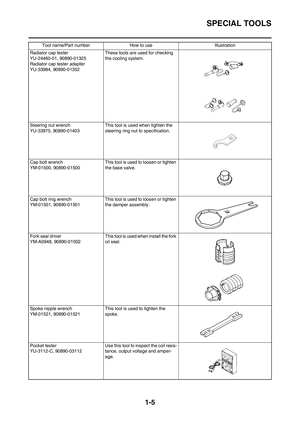
sor:
YM-4019/90890-04019
Stem-to-guide clearance = valve
guide inside diameter "a" -
valve stem diameter "b"
Clearance (stem to
guide):
Intake:
0.010–0.037 mm
(0.0004–0.0015 in)
:0.08 mm
(0.003 in)
Exhaust:
0.025–0.052 mm
(0.0010–0.0020 in)
:0.10 mm
(0.004 in)
Valve guide remover:
Intake:4.0 mm (0.16 in)
YM-4111/90890-04111
Exhaust:4.5 mm (0.18
in)
YM-4116/90890-04116
Valve guide installer:
Intake:4.0 mm (0.16 in)
YM-4112/90890-04112
Exhaust:4.5 mm (0.18
in)
YM-4117/90890-04117
Valve guide reamer:
Intake:4.0 mm (0.16 in)
YM-4113/90890-04113
Exhaust:4.5 mm (0.18
in)
YM-4118/90890-04118
Page 93 of 190

4-23
VALVES AND VALVE SPRINGS
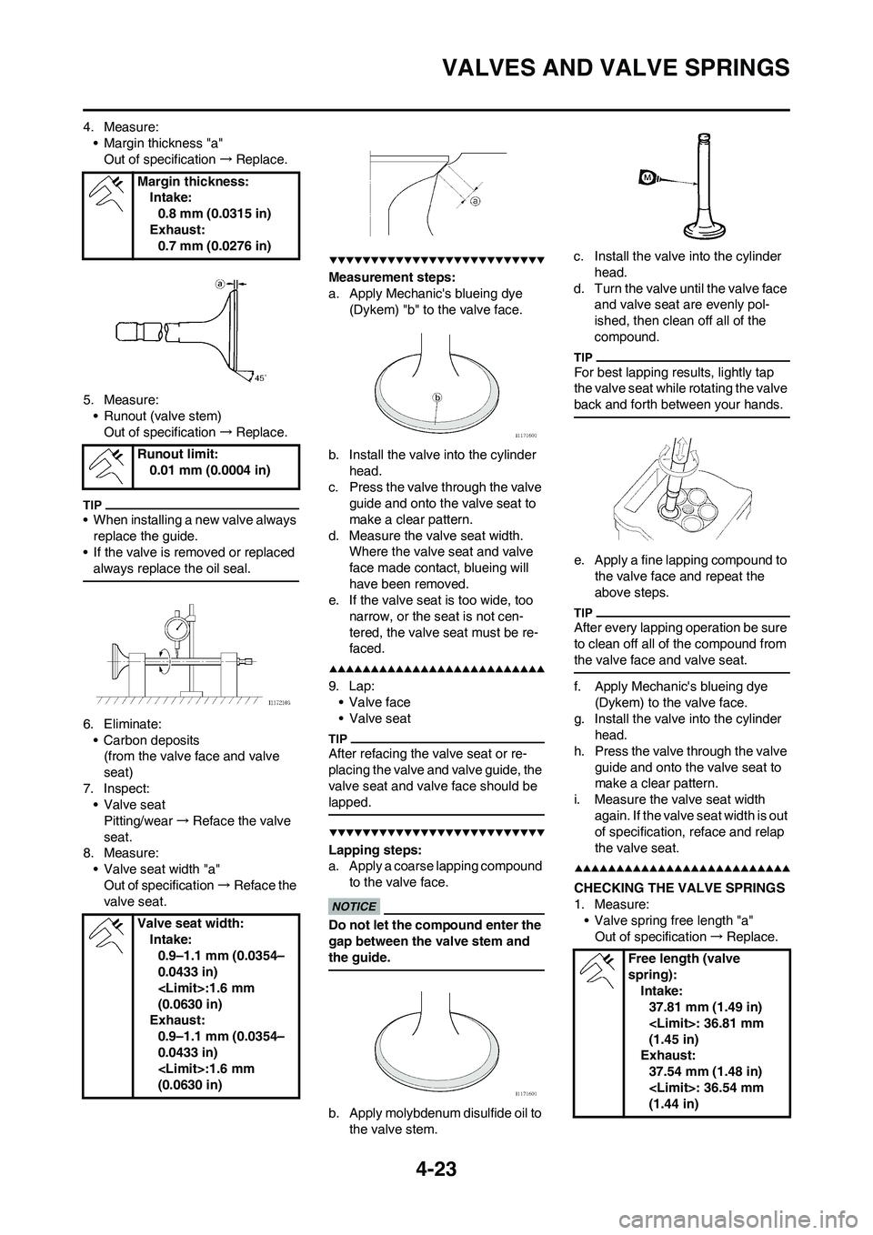
4. Measure:
• Margin thickness "a"
Out of specification→Replace.
5. Measure:
• Runout (valve stem)
Out of specification→Replace.
• When installing a new valve always
replace the guide.
• If the valve is removed or replaced
always replace the oil seal.
6. Eliminate:
• Carbon deposits
(from the valve face and valve
seat)
7. Inspect:
•Valve seat
Pitting/wear→Reface the valve
seat.
8. Measure:
• Valve seat width "a"
Out of specification→Reface the
valve seat.
Measurement steps:
a. Apply Mechanic's blueing dye
(Dykem) "b" to the valve face.
b. Install the valve into the cylinder
head.
c. Press the valve through the valve
guide and onto the valve seat to
make a clear pattern.
d. Measure the valve seat width.
Where the valve seat and valve
face made contact, blueing will
have been removed.
e. If the valve seat is too wide, too
narrow, or the seat is not cen-
tered, the valve seat must be re-
faced.
9. Lap:
• Valve face
• Valve seat
After refacing the valve seat or re-
placing the valve and valve guide, the
valve seat and valve face should be
lapped.
Lapping steps:
a. Apply a coarse lapping compound
to the valve face.
Do not let the compound enter the
gap between the valve stem and
the guide.
b. Apply molybdenum disulfide oil to
the valve stem.c. Install the valve into the cylinder
head.
d. Turn the valve until the valve face
and valve seat are evenly pol-
ished, then clean off all of the
compound.
For best lapping results, lightly tap
the valve seat while rotating the valve
back and forth between your hands.
e. Apply a fine lapping compound to
the valve face and repeat the
above steps.
After every lapping operation be sure
to clean off all of the compound from
the valve face and valve seat.
f. Apply Mechanic's blueing dye
(Dykem) to the valve face.
g. Install the valve into the cylinder
head.
h. Press the valve through the valve
guide and onto the valve seat to
make a clear pattern.
i. Measure the valve seat width
again. If the valve seat width is out
of specification, reface and relap
the valve seat.
CHECKING THE VALVE SPRINGS
1. Measure:
• Valve spring free length "a"
Out of specification→Replace. Margin thickness:
Intake:
0.8 mm (0.0315 in)
Exhaust:
0.7 mm (0.0276 in)
Runout limit:
0.01 mm (0.0004 in)
Valve seat width:
Intake:
0.9–1.1 mm (0.0354–
0.0433 in)
:1.6 mm
(0.0630 in)
Exhaust:
0.9–1.1 mm (0.0354–
0.0433 in)
:1.6 mm
(0.0630 in)
Free length (valve
spring):
Intake:
37.81 mm (1.49 in)
: 36.81 mm
(1.45 in)
Exhaust:
37.54 mm (1.48 in)
: 36.54 mm
(1.44 in)
Page 94 of 190

4-24
VALVES AND VALVE SPRINGS
2. Measure:
• Compressed spring force "a"
Out of specification→Replace.
b. Installed length
3. Measure:
• Spring tilt "a"
Out of specification→Replace.
CHECKING THE VALVE LIFTERS
1. Inspect:
• Valve lifter
Scratches/damage→Replace
both lifters and cylinder head.INSTALLING THE VALVES
1. Apply:
• Molybdenum disulfide oil
Onto the valve stem and valve
stem seal.
2. Install:
•Valve "1"
• Valve spring seat "2"
• Valve stem seal "3"
• Valve spring "4"
• Valve spring retainer "5"
To cylinder head.
• Make sure that each valve is in-
stalled in its original place, also re-
ferring to the painted color as
follows.
Intake (middle) "a": Orange
Intake (right/left) "b": Green
Exhaust "c": Purple
• Install the valve springs with the
larger pitch "d" facing upward.
e. Smaller pitch
3. Install:
• Valve cotter
While compressing the valve spring
with a valve spring compressor "1" in-
stall the valve cotters.
4. To secure the valve cotters onto
the valve stem, lightly tap the
valve tip with a piece of wood.
Hitting the valve tip with excessive
force could damage the valve.
5. Install:
• Adjusting pad "1"
• Valve lifter "2"
• Apply the molybdenum disulfide oil
on the valve stem end.
• Apply the engine oil on the valve lift-
ers.
• Valve lifter must turn smoothly
when rotated with a finger.
• Be careful to reinstall valve lifters
and pads in their original place.
Compressed spring
force:
Intake:
99–114 N at 29.13 mm
(9.9–11.4 kg at 29.13
mm, 22.27–25.57 lb at
1.15 in)
Exhaust:
126–144 N at 29.30
mm (12.6–14.4 kg at
29.30 mm, 28.44–
32.41 lb at 1.15 in)
Spring tilt limit:
Intake:
2.5°/1.7 mm (0.067 in)
Exhaust:
2.5°/1.6 mm (0.063 in)
Valve spring compres-
sor:
YM-4019/90890-04019
Page 95 of 190
4-25
CYLINDER AND PISTON
CYLINDER AND PISTON
REMOVING THE CYLINDER AND PISTON
Order Part name Q'ty Remarks
Cylinder head Refer to "CYLINDER HEAD" section.
1 Bolt (cylinder) 1
2Cylinder 1
3 Piston pin clip 2 Refer to removal section.
4 Piston pin 1 Refer to removal section.
5 Piston 1 Refer to removal section.
6 Piston ring set 1 Refer to removal section.
Page 96 of 190

4-26
CYLINDER AND PISTON
REMOVING THE PISTON AND
PISTON RING
1. Remove:
• Piston pin clip "1"
• Piston pin "2"
•Piston "3"
• Put identification marks on each
piston head for reference during re-
installation.
• Before removing each piston pin,
deburr the clip groove and pin hole
area. If the piston pin groove is de-
burred and the piston pin is still dif-
ficult to remove, use the piston pin
puller set "4".
Do not use a hammer to drive the
piston pin out.
2. Remove:
• Piston ring "1"
Spread the end gaps apart while at
the same time lifting the piston ring
over the top of the piston crown, as
shown in the illustration.
CHECKING THE CYLINDER AND
PISTON
1. Inspect:
• Cylinder and piston walls
Vertical scratches→Replace cyl-
inder and piston.2. Measure:
• Piston-to-cylinder clearance
Measurement steps:
a. Measure the cylinder bore "C"
with a cylinder bore gauge.
Measure the cylinder bore "C" in par-
allel to and at right angles to the
crankshaft. Then, find the average of
the measurements.
b. If out of specification, replace the
cylinder, and replace the piston
and piston rings as set.
c. Measure the piston skirt diameter
"P" with a micrometer.
a. 8 mm (0.31 in) from the piston
bottom edge
d. If out of specification, replace the
piston and piston rings as a set.
e. Calculate the piston-to-cylinder
clearance with following formula:f. If out of specification, replace the
cylinder, and replace the piston
and piston rings as set.
CHECKING THE PISTON RING
1. Measure:
• Ring side clearance
Use a feeler gauge "1".
Out of specification→Replace the
piston and rings as a set.
Clean carbon from the piston ring
grooves and rings before measuring
the side clearance.
2. Position:
• Piston ring
(in cylinder)
Insert a ring into the cylinder and
push it approximately 10 mm (0.39 in)
into the cylinder. Push the ring with
the piston crown so that the ring will
be at a right angle to the cylinder
bore.
a. 10 mm (0.39 in) Piston pin puller set:
YU-1304/90890-01304
Cylinder bore
"C"77.00–77.01
mm (3.0315–
3.0319 in)
Taper limit "T"0.05 mm (0.002
in)
Out of round
"R"0.05 mm (0.002
in)
"C" = Maximum D
"T" = (Maximum D
1 or D2) - (Max-
imum D
5 or D6)
"R" = (Maximum D
1, D3 or D5) -
(Minimum D
2, D4 or D6)
Piston size "P"
Standard76.955–76.970
mm (3.0297–
3.0303 in)
Piston-to-cylinder clearance =
Cylinder bore "C" - Piston skirt
diameter "P"
Piston-to-cylinder clear-
ance:
0.030–0.055 mm
(0.0012–0.0022 in)
:0.1 mm (0.004
in)
Side clearance:
Standard
Top
ring0.030–0.065
mm (0.0012–
0.0026 in)0.12
mm
(0.005
in)
2nd
ring0.020–0.055
mm (0.0008–
0.0022 in)0.12
mm
(0.005
in)