Page 116 of 150

8-36
1
2
3
4
5
6
78
9
10
11
EBU24393
Checking the front brake lever free play
The brake lever free play must be checked at the
intervals specified in the periodic maintenance and
lubrication chart. The brake lever should have no
free play as shown. If there is free play, have a
Yamaha dealer check the brake system.
WARNING
EWB02471
Operating with improperly serviced or adjust-
ed brakes could cause loss of braking ability,
which could lead to an accident.
After servicing:
�
Make sure the brakes operate smoothly and
that there is no free play.
�
Make sure the brakes do not drag.
�
Make sure the brakes are not spongy. All air
must be bled from the brake system.
Replacement of brake components requires
professional knowledge. These procedures
should be performed by a Yamaha dealer.
EBU24611
Checking the brake pedal position
The brake pedal position must be checked and, if
necessary, adjusted at the intervals specified in
the periodic maintenance and lubrication chart.
The top of the brake pedal should be positioned
11.7 mm (0.46 in) below the top of the footrest as
shown. If the brake pedal is not positioned as spec-
ified, have a Yamaha dealer adjust it.
1. Brake lever free play
1
Page 117 of 150
8-37
1
2
3
4
5
6
78
9
10
11
WARNING
EWB02110
Operating with improperly serviced or adjust-
ed brakes could cause loss of braking ability,
which could lead to an accident.
After servicing:
�
Make sure the brakes operate smoothly and
that the brake pedal position is correct.
�
Make sure the brakes do not drag.
�
Make sure the brakes are not spongy. All air
must be bled from the brake system.
Replacement of brake components requires
professional knowledge. These procedures
should be performed by a Yamaha dealer.
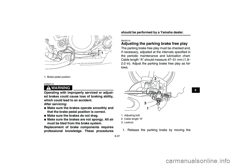
EBU24710
Adjusting the parking brake free play
The parking brake free play must be checked and,
if necessary, adjusted at the intervals specified in
the periodic maintenance and lubrication chart.
Cable length “A” should measure 47–51 mm (1.9–
2.0 in). Adjust the parking brake free play as fol-
lows.
1. Release the parking brake by moving the
1. Brake pedal position
1
1. Adjusting bolt
2. Cable length “A”
3. Locknut
2
3
1
Page 118 of 150

8-38
1
2
3
4
5
6
78
9
10
11
parking brake lever to the right.
2. Fully loosen the locknut and the adjusting bolt
at the rear brake caliper.
3. Loosen the locknut on the brake cable.
4. Turn the adjusting nut on the brake cable in di-
rection (a) to increase the cable length, and in
direction (b) to decrease it.
TIP
If the cable length cannot be adjusted to specifica-
tion, consult a Yamaha dealer.
5. Tighten the locknut on the brake cable.6. Turn in the adjusting bolt at the rear brake cal-
iper until it feels tight, then turn it out 1/8 turn
and tighten its locknut to the specified torque.
NOTICE
ECB00520
When tightening the locknut, hold the adjust-
ing bolt with a wrench so that it does not turn
together with the locknut.
WARNING
EWB02090
Operating with improperly serviced or adjust-
ed brakes could cause the brakes to malfunc-
tion, resulting in reduced braking
performance. This could increase the chance
of a collision or accident. After adjusting the
parking brake free play, block the rear of the
ATV off the ground and spin the rear wheels.
Check to make sure there is no brake drag. If
brake drag is noticed, perform the adjustment
again.
1. Locknut
2. Adjusting nut
(a)
(b)
12
Tightening torque:
Locknut (rear brake caliper):
16 Nm (1.6 m·kgf, 12 ft·lbf)
Page 124 of 150
8-44
1
2
3
4
5
6
78
9
10
11
WARNING
EWB02130
Inspect cables frequently and replace if dam-
aged. Corrosion can result when the cable
sheaths become damaged, and cables can
also become frayed or kinked, which could re-
strict the operation of controls and lead to an
accident or injury.
EBU24922
Checking and lubricating the brake and
clutch levers
The operation of the brake and clutch levers
should be checked before each ride, and the lever
pivots should be lubricated if necessary.
Brake lever
Clutch lever
Recommended lubricants:
Brake lever:
Silicone grease
Clutch lever:
Lithium-soap-based grease
Page 127 of 150
 battery. There is no need to check
the electrolyte or to add distilled")
8-47
1
2
3
4
5
6
78
9
10
11
Right side
EBU25224
Battery
This model is equipped with a VRLA (Valve Regu-
lated Lead Acid) battery. There is no need to check
the electrolyte or to add distilled water. However,
the battery lead connections need to be checked
and, if necessary, tightened.
NOTICE
ECB00620
Never attempt to remove the battery cell seals,
as this would permanently damage the battery.WARNING
EWB02160
Battery electrolyte is poisonous and danger-
ous, as it contains sulfuric acid, which can
cause severe burns. Avoid contact with skin,
eyes or clothing. Always shield your eyes
when working near batteries.
Antidote:
EXTERNAL: Flush with water.
INTERNAL: Drink large quantities of water or
milk. Follow with milk of magnesia, beaten egg
or vegetable oil. Call a physician immediately.
EYES: Flush with water for 15 minutes and get
prompt medical attention.
Batteries produce explosive gases. Keep
sparks, flame, cigarettes or other sources of ig-
nition away. Ventilate when charging or using
in an enclosed space.
KEEP OUT OF REACH OF CHILDREN.
To remove the battery
1. Remove the seat. (See page 4-11.)
2. Unhook the band securing the owner’s tool kit,
and then remove the battery holding plate by
removing the bolts.
3. Disconnect the negative battery lead first,
1. Upper grease nipple
2. Lower grease nipple
2 1
Page 130 of 150
8-50
1
2
3
4
5
6
78
9
10
11
NOTICE
ECB00640
To prevent accidental short-circuiting, turn off
the main switch when checking or replacing a
fuse.
2. Remove the blown fuse, and then install a
new fuse of the specified amperage.
WARNING
EWB02171
Always use a fuse of the specified rating, and
never use a substitute object in place of the
proper fuse. An improper fuse or a substitute
object can cause damage to the electrical sys-
tem, which could lead to a fire.
3. Turn the key to “ON” and turn on the electrical
circuits to check if the devices operate.
4. If the fuse immediately blows again, have a
Yamaha dealer check the electrical system.
EBU25440
Replacing a headlight bulb
If a headlight bulb burns out, replace it as follows.
1. Remove the headlight unit by removing the
bolts.
2. Disconnect the headlight coupler.
3. Remove the headlight bulb holder cover. Specified fuse:
15.0 A
1. Headlight assembly
2. Bolt
21
Page 131 of 150
8-51
1
2
3
4
5
6
78
9
10
11
4. Remove the headlight bulb holder by pushing
it in and turning it counterclockwise, and then
remove the defective bulb.WARNING
EWB02230
Do not touch a headlight bulb when it is on or
immediately after it is turned off. You can be
burned or a fire could start if the bulb touches
something flammable. Wait for the bulb to cool
before touching or removing it.
5. Place a new headlight bulb into position.
1. Headlight bulb holder cover
2. Headlight coupler
1
2
1. Headlight bulb holder
1
Page 134 of 150

8-54
1
2
3
4
5
6
78
9
10
11
wheel.
Front
3. Lower the ATV to the ground.
4. Tighten the wheel nuts to the specified
torques.
EBU25740
Troubleshooting
Although Yamaha ATVs receive a thorough in-
spection before shipment from the factory, trouble
may occur during operation. Any problem in the fu-
el, compression, or ignition systems, for example,
can cause poor starting and loss of power.
The following troubleshooting charts represent
quick and easy procedures for checking these vital
systems yourself. However, should your ATV re-
quire any repair, take it to a Yamaha dealer, whose
skilled technicians have the necessary tools, expe-
rience, and know-how to service the ATV properly.
Use only genuine Yamaha replacement parts. Im-
itation parts may look like Yamaha parts, but they
are often inferior, have a shorter service life and
can lead to expensive repair bills.WARNING
EWB02280
Do not smoke when checking the fuel system.
Fuel can ignite or explode, causing severe inju-
ry or property damage. Make sure there are no
open flames or sparks in the area, including pi-
lot lights from water heaters or furnaces.
1. Arrow mark
Tightening torques:
Front wheel nut:
45 Nm (4.5 m·kgf, 33 ft·lbf)
Rear wheel nut:
45 Nm (4.5 m·kgf, 33 ft·lbf)