Page 23 of 150

4-3
1
2
34
5
6
7
8
9
10
11
EBU18100
Start switch “”
Push this switch to crank the engine with the start-
er.
NOTICE
ECB00050
See the starting instructions on page 6-1 prior
to starting the engine.
EBU18151
Light switch “/ /OFF”
Set this switch to “” to turn on the low beams
and the taillight. Set the switch to “” to turn on
the high beams and the taillight. Set the switch to
“OFF” to turn off all the lights.
NOTICE
ECB00040
Do not use the headlights with the engine
turned off for an extended period of time, oth-
erwise the battery may discharge to the point
that the starter motor will not operate properly.
If this should happen, remove the battery and
recharge it.
EBU18280
Throttle lever
Once the engine is running, movement of the throt-tle lever will increase the engine speed.
Regulate the speed of the ATV by varying the
throttle position. Because the throttle is spring-
loaded, the ATV will decelerate, and the engine will
return to an idle any time the hand is removed from
the throttle lever.
Before starting the engine, check the throttle to be
sure it is operating smoothly. Make sure it returns
to the idle position as soon as the lever is released.
WARNING
EWB00250
Malfunction of the throttle could make it diffi-
cult to speed up or slow down when you need
1. Throttle lever
Page 24 of 150

4-4
1
2
34
5
6
7
8
9
10
11
to. This could cause an accident. Check the op-
eration of the throttle lever before you start the
engine. If the throttle does not work smoothly,
check for the cause. Correct the problem be-
fore riding the ATV or consult a Yamaha dealer.
EBU18321
Speed limiter
Your ATV was delivered with an adjustable speed
limiter. The speed limiter keeps the throttle from
fully opening, even when the throttle lever is
pushed to the maximum.
1. Loosen the locknut.
2. To increase the maximum engine power avail-
able and the maximum speed of the ATV, turn
the adjusting screw in direction (a). To de-
crease the maximum engine power available
and the maximum speed of the ATV, turn the
adjusting screw in direction (b).3. Tighten the locknut.WARNING
EWB00240
Improper adjustment of the speed limiter and
throttle could cause throttle cable damage or
improper throttle operation. You could lose
control, have an accident or be injured. Do not
turn the adjusting screw out more than 12 mm
(0.47 in) or the throttle cable could be dam-
aged. Always make sure the throttle lever free
play is adjusted to 2.0–4.0 mm (0.08–0.16 in).
1. Locknut
2. Adjusting screw
3. No more than 12 mm (0.47 in)3
1
2
(a)
(b)
Page 27 of 150
4-7
1
2
34
5
6
7
8
9
10
11
WARNING
EWB00220
�
Always set the parking brake before starting
the engine. The ATV could start moving un-
expectedly if the parking brake is not ap-
plied. This could cause loss of control or a
collision.
�
Always be sure you have released the park-
ing brake before you begin to ride. The brake
could overheat if you ride the ATV without re-
leasing the parking brake. You could lose
braking performance which could cause an
accident. You could also wear out the brakes
prematurely.
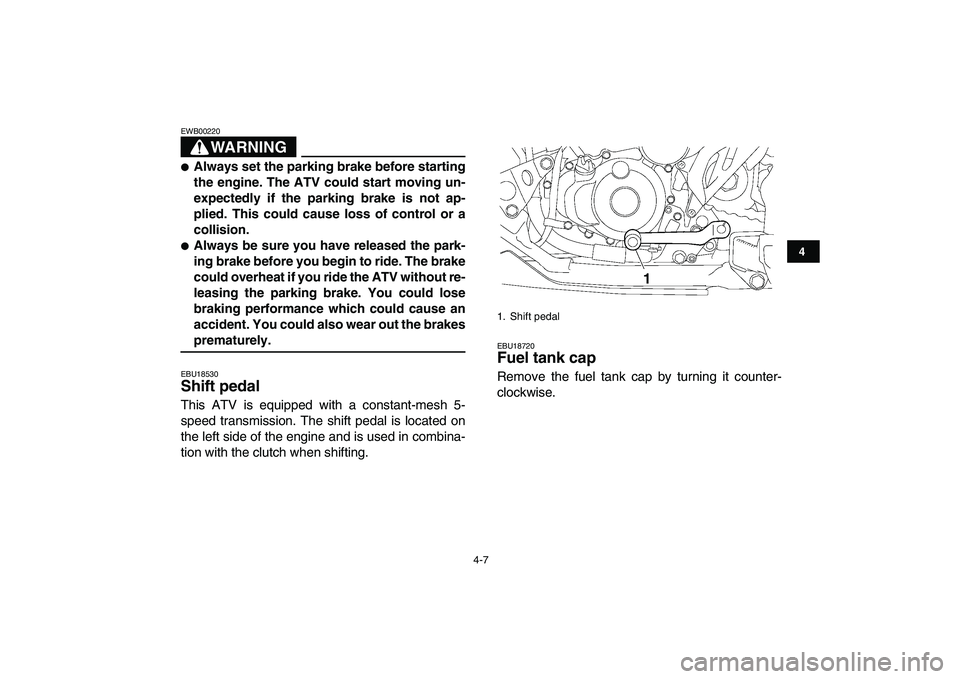
EBU18530
Shift pedal
This ATV is equipped with a constant-mesh 5-
speed transmission. The shift pedal is located on
the left side of the engine and is used in combina-
tion with the clutch when shifting.
EBU18720
Fuel tank cap
Remove the fuel tank cap by turning it counter-
clockwise.
1. Shift pedal
1
Page 29 of 150

4-9
1
2
34
5
6
7
8
9
10
11
of gasoline or higher octane grade.
NOTICE
ECB00070
Use only unleaded gasoline. The use of leaded
gasoline will cause severe damage to internal
engine parts, such as the valves and piston
rings, as well as to the exhaust system.
WARNING
EWB00310
�
Do not overfill the fuel tank. Fuel expands
when it heats up. If the fuel tank is overfilled,
fuel could spill out due to heat from the en-
gine or the sun.
�
Be careful not to spill fuel, especially on the
engine or exhaust pipe which can cause a
fire and severe injury. Wipe up any spilled
fuel immediately.
�
Do not refuel right after the engine has been
running and is still very hot.
�
Be sure the fuel tank cap is closed securely.
EBU18820
Fuel cock
The fuel cock supplies fuel from the tank to the car-
buretor while also filtering it.The fuel cock lever positions are explained as fol-
lows and shown in the illustrations.
OFF
With the fuel cock lever in this position, fuel will not
flow. Always turn the fuel cock lever to this position
when the engine is not running.
1. Arrow mark positioned over “OFF”
1
Page 32 of 150

4-12
1
2
34
5
6
7
8
9
10
11
EBU27903
Adjusting the front shock absorber
assemblies
These shock absorber assemblies are equipped
with a spring preload adjusting nut, a rebound
damping force adjusting screw, with a compres-
sion damping force adjusting bolt (for fast com-
pression damping), and a compression damping
force adjusting screw (for slow compression damp-
ing).WARNING
EWB00410
These shock absorber assemblies contain
highly pressurized nitrogen gas. Read and un-
derstand the following information before han-
dling the shock absorber assemblies.
�
Do not tamper with or attempt to open the
cylinder assemblies.
�
Do not subject the shock absorber assem-
blies to an open flame or other high heat
source. This may cause the unit to explode
due to excessive gas pressure.
�
Do not deform or damage the cylinders in
any way. Cylinder damage will result in poor
damping performance.
�
Do not dispose of a damaged or worn out
shock absorber assembly yourself. Take the
shock absorber assembly to a Yamaha deal-
er for any service.
Spring preload
1. Loosen the locknut.
2. Turn the adjusting nut in direction (a) to in-
crease the spring preload and thereby harden
the suspension, and in direction (b) to de-
crease the spring preload and thereby soften
1. Projection
2. Seat holder
1
2
Page 36 of 150

4-16
1
2
34
5
6
7
8
9
10
11
NOTICE
ECB00090
Never turn an adjusting mechanism beyond
the minimum and maximum settings.
TIP
Although the total number of clicks of a damping
force adjusting mechanism may not exactly match
the above specifications due to small differences in
production, the actual number of clicks always rep-
resents the entire adjusting range. To obtain a pre-
cise adjustment, it would be advisable to check the
number of clicks of each damping force adjusting
mechanism and to modify the specifications as
necessary.
WARNING
EWB00420
�
Suspension components become hot during
operation. Never touch the compression
damping force adjusting screw, the rebound
damping force adjusting screw or the oil res-
ervoir with your bare hand or skin until sus-
pension components have cooled.
�
Always adjust the shock absorber assem-
blies on the left and right side to the same
1. Compression damping force adjusting screw (for slow
compression damping)
Compression damping setting (for slow com-
pression damping):
Minimum (soft):
20 click(s) in direction (b)*
Standard:
10 click(s) in direction (b)*
Maximum (hard):
1 click(s) in direction (b)*
* With the adjusting screw fully turned in di-
rection (a)
(b)(a)
1
Page 37 of 150

4-17
1
2
34
5
6
7
8
9
10
11
setting.
WARNING
EWB00400
Always adjust the shock absorber assemblies
on the left and right side to the same setting.
Uneven adjustment can cause poor handling
and loss of stability, which could lead to an ac-
cident.
EBU27923
Adjusting the rear shock absorber
assembly
This shock absorber assembly is equipped with a
spring preload adjusting nut, a rebound damping
force adjusting screw, with a compression damp-
ing force adjusting bolt (for fast compression
damping), and a compression damping force ad-
justing screw (for slow compression damping).
WARNING
EWB00430
This shock absorber assembly contains highly
pressurized nitrogen gas. Read and under-
stand the following information before han-
dling the shock absorber assembly.
�
Do not tamper with or attempt to open thecylinder assembly.
�
Do not subject the shock absorber assembly
to an open flame or other high heat source.
This may cause the unit to explode due to ex-
cessive gas pressure.
�
Do not deform or damage the cylinder in any
way. Cylinder damage will result in poor
damping performance.
�
Do not dispose of a damaged or worn out
shock absorber assembly yourself. Take the
shock absorber assembly to a Yamaha deal-
er for any service.
Spring preload
1. Remove the seat. (See page 4-11.)
2. Loosen the clamp screw at the carburetor
side, and then disconnect the air intake duct.
Page 43 of 150

4-23
1
2
34
5
6
7
8
9
10
11
NOTICE
ECB00090
Never turn an adjusting mechanism beyond
the minimum and maximum settings.
TIP
Although the total number of clicks of a damping
force adjusting mechanism may not exactly match
the above specifications due to small differences in
production, the actual number of clicks always rep-
resents the entire adjusting range. To obtain a pre-
cise adjustment, it would be advisable to check the
number of clicks of each damping force adjusting
mechanism and to modify the specifications as
necessary.
3. Install the seat.WARNING
EWB00440
Suspension components become hot during
operation. Never touch the compression
damping force adjusting screw, the rebound
damping force adjusting screw or the oil reser-
voir with your bare hand or skin until suspen-
sion components have cooled.
1. Compression damping force adjusting screw (for slow
compression damping)
Compression damping setting (for slow com-
pression damping):
Minimum (soft):
20 click(s) in direction (b)*
Standard:
11 click(s) in direction (b)*
Maximum (hard):
1 click(s) in direction (b)*
* With the adjusting screw fully turned in di-
rection (a)
(b)(a)
1