Page 49 of 88
PERIODIC MAINTENANCE AND ADJUSTMENT
6-9
6
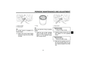
TIPAn oil filter wrench is available at aYamaha dealer.
6. Apply a thin coat of clean engine
oil to the O-ring of the new oil filter
cartridge.
TIPMake sure that the O-ring is properlyseated.
7. Install the new oil filter cartridge
with an oil filter wrench, and then
tighten it to the specified torque
with a torque wrench.8. Install the engine oil drain bolt, and
then tighten it to the specified
torque.
9. Refill with the specified amount of
the recommended engine oil, and
then install and tighten the oil filler
cap.
1. Oil filter cartridge
2. Oil filter wrench
1. O-ring
1. Torque wrench
Tightening torque:
Oil filter cartridge:
17 Nm (1.7 m·kgf, 12 ft·lbf)
Tightening torque:
Engine oil drain bolt:
43 Nm (4.3 m·kgf, 31 ft·lbf)
U11CE2E0.book Page 9 Friday, August 29, 2008 9:28 AM
Page 50 of 88

PERIODIC MAINTENANCE AND ADJUSTMENT
6-10
6
TIPBe sure to wipe off spilled oil on any
parts after the engine and exhaust sys-tem have cooled down.NOTICE
ECA11620
�
In order to prevent clutch slip-
page (since the engine oil also
lubricates the clutch), do not
mix any chemical additives. Do
not use oils with a diesel speci-
fication of “CD” or oils of a high-
er quality than specified. In
addition, do not use oils labeled
“ENERGY CONSERVING II” or
higher.
�
Make sure that no foreign mate-rial enters the crankcase.10. Start the engine, and then let it idle
for several minutes while checking
it for oil leakage. If oil is leaking, im-
mediately turn the engine off and
check for the cause.
TIPAfter the engine is started, the engine
oil level warning light should go off if theoil level is sufficient.NOTICE
ECA10400
If the oil level warning light flickers
or remains on, immediately turn the
engine off and have a Yamaha dealercheck the vehicle.11. Turn the engine off, and then
check the oil level and correct it if
necessary.
Recommended engine oil:
See page 8-1.
Oil quantity:
Without oil filter cartridge replace-
ment:
3.20 L (3.38 US qt, 2.82 Imp.qt)
With oil filter cartridge replacement:
3.40 L (3.59 US qt, 2.99 Imp.qt)
1.“CD” specification
2.“ENERGY CONSERVING II”
1
2
U11CE2E0.book Page 10 Friday, August 29, 2008 9:28 AM
Page 51 of 88

PERIODIC MAINTENANCE AND ADJUSTMENT
6-11
6
EAU20070
Coolant The coolant level should be checked
before each ride. In addition, the cool-
ant must be changed at the intervals
specified in the periodic maintenance
and lubrication chart.
EAU42632
To check the coolant level
1. Place the vehicle on a level sur-
face and hold it in an upright posi-
tion.TIP�
The coolant level must be checked
on a cold engine since the level
varies with engine temperature.
�
Make sure that the vehicle is posi-
tioned straight up when checking
the coolant level. A slight tilt to theside can result in a false reading.
2. Check the coolant level in the cool-
ant reservoir.
TIPThe coolant should be between theminimum and maximum level marks.3. If the coolant is at or below the
minimum level mark, remove pan-
el A. (See page 6-6.)
4. Remove the coolant reservoir cap,
add coolant to the maximum level
mark, and then install the reservoir
cap. WARNING! Remove only
the coolant reservoir cap. Never
attempt to remove the radiator
cap when the engine is hot.
[EWA15161]
NOTICE: If coolant is not
available, use distilled water or
soft tap water instead. Do not
use hard water or salt water
since it is harmful to the engine.
If water has been used insteadof coolant, replace it with cool-
ant as soon as possible, other-
wise the cooling system will not
be protected against frost and
corrosion. If water has been
added to the coolant, have a
Yamaha dealer check the anti-
freeze content of the coolant as
soon as possible, otherwise the
effectiveness of the coolant will
be reduced.
[ECA10472]
5. Install the panel.
1. Coolant reservoir
2. Maximum level mark
3. Minimum level mark
1. Coolant reservoir cap
Coolant reservoir capacity (up to the
maximum level mark):
0.45 L (0.48 US qt, 0.40 Imp.qt)
U11CE2E0.book Page 11 Friday, August 29, 2008 9:28 AM
Page 52 of 88

PERIODIC MAINTENANCE AND ADJUSTMENT
6-12
6
TIPMake sure that the coolant reservoir
breather hose is properly routedthrough the guide.
EAU33031
Changing the coolant
The coolant must be changed at the in-
tervals specified in the periodic mainte-
nance and lubrication chart. Have a
Yamaha dealer change the coolant.
WARNING! Never attempt to remove
the radiator cap when the engine is
hot.
[EWA10381]EAU42442
Replacing the air filter element The air filter element should be re-
placed at the intervals specified in the
periodic maintenance and lubrication
chart. Replace the air filter element
more frequently if you are riding in un-
usually wet or dusty areas.
1. Remove the air filter case cover by
removing the bolts.
2. Pull the air filter element out.3. Insert a new air filter element into
the air filter case. NOTICE: Make
sure that the air filter element is
properly seated in the air filter
case. The engine should never
be operated without the air filter
element installed, otherwise the
piston(s) and/or cylinder(s) may
become excessively worn.
[ECA10481]
4. Install the air filter case cover by in-
stalling the bolts.
1. Guide
2. Coolant reservoir breather hose
1. Air filter case cover
2. Bolt
1. Air filter element
U11CE2E0.book Page 12 Friday, August 29, 2008 9:28 AM
Page 53 of 88
 at the
throttle grip. Periodicall")
PERIODIC MAINTENANCE AND ADJUSTMENT
6-13
6
EAU21382
Checking the throttle cable
free play The throttle cable free play should mea-
sure 4.0–6.0 mm (0.16–0.24 in) at the
throttle grip. Periodically check the
throttle cable free play and, if neces-
sary, have a Yamaha dealer adjust it.
EAU21401
Valve clearance The valve clearance changes with use,
resulting in improper air-fuel mixture
and/or engine noise. To prevent this
from occurring, the valve clearance
must be adjusted by a Yamaha dealer
at the intervals specified in the periodic
maintenance and lubrication chart.
EAU21562
Tires To maximize the performance, durabil-
ity, and safe operation of your motor-
cycle, note the following points
regarding the specified tires.
Tire air pressure
The tire air pressure should be checked
and, if necessary, adjusted before each
ride.
WARNING
EWA10501
Operation of this vehicle with im-
proper tire pressure may cause se-
vere injury or death from loss of
control.�
The tire air pressure must be
checked and adjusted on cold
tires (i.e., when the temperature
of the tires equals the ambient
temperature).
�
The tire air pressure must be ad-
justed in accordance with the
riding speed and with the total
weight of rider, passenger, car-
go, and accessories approvedfor this model.
1. Throttle cable free play
U11CE2E0.book Page 13 Friday, August 29, 2008 9:28 AM
Page 54 of 88

PERIODIC MAINTENANCE AND ADJUSTMENT
6-14
6
WARNING
EWA10511
Never overload your vehicle. Opera-
tion of an overloaded vehicle couldcause an accident.Tire inspection
The tires must be checked before each
ride. If the center tread depth reaches
the specified limit, if the tire has a nail or
glass fragments in it, or if the sidewall is
cracked, have a Yamaha dealer re-
place the tire immediately.
TIPThe tire tread depth limits may differ
from country to country. Always complywith the local regulations.Tire information
This motorcycle is equipped with cast
wheels and tubeless tires.
WARNING
EWA10461
The front and rear tires should be of
the same make and design, other-
wise the handling characteristics of
the vehicle may be different, whichcould lead to an accident.
After extensive tests, only the tires list-
ed below have been approved for this
model by Yamaha Motor Co., Ltd.
Tire air pressure (measured on cold
tires):
0–90 kg (0–198 lb):
Front:
250 kPa (2.50 kgf/cm², 36 psi)
Rear:
280 kPa (2.80 kgf/cm², 41 psi)
90–210 kg (198–463 lb):
Front:
250 kPa (2.50 kgf/cm², 36 psi)
Rear:
280 kPa (2.80 kgf/cm², 41 psi)
Maximum load*:
210 kg (463 lb)
* Total weight of rider, passenger, car-
go and accessories
1. Tire sidewall
2. Tire tread depthMinimum tire tread depth (front and
rear):
1.6 mm (0.06 in)
Front tire:
Size:
130/90 16M/C 67H
Manufacturer/model:
DUNLOP/D404F X
BRIDGESTONE/EXEDRA G721
Rear tire:
Size:
170/70B 16M/C 75H
Manufacturer/model:
DUNLOP/K555
BRIDGESTONE/EXEDRA G722 G
U11CE2E0.book Page 14 Friday, August 29, 2008 9:28 AM
Page 55 of 88

PERIODIC MAINTENANCE AND ADJUSTMENT
6-15
6
WARNING
EWA10470
�
Have a Yamaha dealer replace
excessively worn tires. Besides
being illegal, operating the vehi-
cle with excessively worn tires
decreases riding stability and
can lead to loss of control.
�
The replacement of all wheel
and brake related parts, includ-
ing the tires, should be left to a
Yamaha dealer, who has the
necessary professional knowl-edge and experience.
EAU21960
Cast wheels To maximize the performance, durabil-
ity, and safe operation of your vehicle,
note the following points regarding the
specified wheels.�
The wheel rims should be checked
for cracks, bends or warpage be-
fore each ride. If any damage is
found, have a Yamaha dealer re-
place the wheel. Do not attempt
even the smallest repair to the
wheel. A deformed or cracked
wheel must be replaced.
�
The wheel should be balanced
whenever either the tire or wheel
has been changed or replaced. An
unbalanced wheel can result in
poor performance, adverse han-
dling characteristics, and a short-
ened tire life.
�
Ride at moderate speeds after
changing a tire since the tire sur-
face must first be “broken in” for it
to develop its optimal characteris-
tics.
EAU22033
Adjusting the clutch lever free
play The clutch lever free play should mea-
sure 5.0–10.0 mm (0.20–0.39 in) as
shown. Periodically check the clutch le-
ver free play and, if necessary, adjust it
as follows.
1. Slide the rubber cover back at the
clutch lever.
2. Loosen the locknut.
3. To increase the clutch lever free
play, turn the clutch lever free play
adjusting bolt in direction (a). To1. Clutch lever free play
2. Locknut (clutch lever)
3. Clutch lever free play adjusting bolt
4. Rubber cover14
2
3
U11CE2E0.book Page 15 Friday, August 29, 2008 9:28 AM
Page 56 of 88
.
4. If the specified clutch lever free
play could be obtained as de-
scribed abo")
PERIODIC MAINTENANCE AND ADJUSTMENT
6-16
6decrease the clutch lever free play,
turn the adjusting bolt in direction
(b).
4. If the specified clutch lever free
play could be obtained as de-
scribed above, tighten the locknut
and skip the rest of the procedure,
otherwise, proceed as follows.
5. Fully turn the adjusting bolt in di-
rection (a) to loosen the clutch ca-
ble.
6. Loosen the locknut further down
the clutch cable.
7. To increase the clutch lever free
play, turn the clutch lever free play
adjusting nut in direction (a). Todecrease the clutch lever free play,
turn the adjusting nut in direction
(b).
8. Tighten both locknuts.
9. Slide the rubber cover to its origi-
nal position.
EAU22093
Adjusting the brake lever free
play The brake lever free play should mea-
sure 2.0–5.0 mm (0.08–0.20 in) as
shown. Periodically check the brake le-
ver free play and, if necessary, adjust it
as follows.
1. Loosen the locknut at the brake le-
ver.
2. To increase the brake lever free
play, turn the brake lever free play
adjusting screw in direction (a). To
decrease the brake lever free play,
turn the adjusting screw in direc-
tion (b).
1. Clutch lever free play adjusting nut (clutch
cable)
2. Locknut (clutch cable)
12
(a)
(b)
1. Locknut
2. Brake lever free play adjusting screw
3. Brake lever free play
3
U11CE2E0.book Page 16 Friday, August 29, 2008 9:28 AM