Page 89 of 226
3-34
ELECTRICAL
ADJUSTING THE HEADLIGHT
BEAMS
1. Adjust:
• Headlight beam (vertically)
Adjusting steps:
a. Turn the adjusting screw "1" in di-
rection "a" or "b".
Direction "a" Headlight beam is
raised.
Direction "b" Headlight beam is
lowered.
Page 90 of 226

TUNING
ENGINE (Except for Canada)
CARBURETOR SETTING
• The air/fuel mixture will vary de-
pending on atmospheric conditions.
Therefore, it is necessary to take
into")
4-1
ENGINE (Except for Canada)
TUNING
ENGINE (Except for Canada)
CARBURETOR SETTING
• The air/fuel mixture will vary de-
pending on atmospheric conditions.
Therefore, it is necessary to take
into consideration the air pressure,
ambient temperature, humidity,
etc., when adjusting the carburetor.
• Perform a test run to check for prop-
er engine performance (e.g., throt-
tle response) and spark plug(-s)
discoloration or fouling. Use these
readings to determine the best pos-
sible carburetor setting.
It is recommended to keep a record of
all carburetor settings and external
conditions (e.g., atmospheric condi-
tions, track/surface conditions, lap
times) to make future carburetor set-
ting easier.
• The carburetor is a part of the
fuel line. Therefore, be sure to in-
stall it in a wellventilated area,
away from flammable objects
and any sources of fire.
• Never look into the carburetor in-
take. Flames may shoot out from
the pipe if the engine backfires
while it is being started. Gasoline
may be discharged from the ac-
celerator pump nozzle when the
carburetor has been removed.
• The carburetor is extremely sen-
sitive to foreign matter (dirt,
sand, water, etc.). During instal-
lation, do not allow foreign mat-
ter to get into the carburetor.
• Always handle the carburetor
and its components carefully.
Even slight scratches, bends or
damage to carburetor parts may
prevent the carburetor from
functioning correctly. Carefully
perform all servicing with the ap-
propriate tools and without ap-
plying excessive force.
• When the engine is stopped or
when riding at no load, do not
open and close the throttle un-
necessarily. Otherwise, too
much fuel may be discharged,
starting may become difficult or
the engine may not run well.• After installing the carburetor,
check that the throttle operates
correctly and opens and closes
smoothly.
ATMOSPHERIC CONDITIONS AND
CARBURETOR SETTINGS
The air density (i.e., concentration of
oxygen in the air) determines the rich-
ness or leanness of the air/fuel mix-
ture.
• Higher temperature expands the air
with its resultant reduced density.
• Higher humidity reduces the
amount of oxygen in the air by so
much of the water vapor in the
same air.
• Lower atmospheric pressure (at a
high altitude) reduces the density of
the air.
EFFECT OF SETTING PARTS IN
RELATION TO THROTTLE VALVE
OPENING
A. Closed
B. Fully open
1. Pilot jet
2. Throttle valve cutaway
3. Jet needle
4. Main jetCONSTRUCTION OF
CARBURETOR AND SETTING
PARTS
The FLATCR carburetor has a prima-
ry main jet. This type of main jet is
perfect for racing machines since it
supplies an even flow of fuel, even at
full load. Use the main jet and the jet
needle to set the carburetor.
1. Jet needle
2. Pilot air jet
3. Needle jet
4. Main jet
5. Pilot jet
ADJUSTING THE MAIN JET
The richness of the air-fuel mixture at
full throttle can be set by changing the
main jet "1".
If the air-fuel mixture is too rich or too
lean, the engine power will drop, re-
sulting in poor acceleration.
Effects of changing the main jet
(reference)
A. Idle
B. Fully open
1. #165
2. #160
3. #162 Air
tem
p.Hu-
midi-
tyAir
pres-
sure
(alti-
tude)Mix-
tureSet-
ting
High HighLow
(high)Rich-
erLean-
er
Low LowHigh
(low)Lean-
erRich-
er
Standard main jet#162
* #160
* For EUROPE
Page 91 of 226

ADJUSTING THE PILOT JET
The richness of the air-fuel mixture
with the throttle open 1/4 or less can
be set by adjusting the pilot jet \"1\".
Effects of adjusting the pil")
4-2
ENGINE (Except for Canada)
ADJUSTING THE PILOT JET
The richness of the air-fuel mixture
with the throttle open 1/4 or less can
be set by adjusting the pilot jet "1".
Effects of adjusting the pilot jet
(reference)
A. Idle
B. Fully open
1. #48
2. #42
3. #45
ADJUSTING THE JET NEEDLE
GROOVE POSITION
Adjusting the jet needle "1" position
affects the acceleration when the
throttle is 1/8 to 3/4 open.
1. Too rich at intermediate speeds
• Rough engine operation is felt
and the engine will not pick up
speed smoothly.
Step up the jet needle clip by one
groove and move down the nee-
dle to lean out the mixture.
2. Too lean at intermediate speeds
• The engine breathes hard and will
not pick up speed quickly.
Step down the jet needle clip by
one groove and move up the nee-
dle to enrich the mixture.Effects of changing the jet needle
groove position (reference)
A. Idle
B. Fully open
1. No.5 groove
2. No.3 groove
3. No.4 groove
ADJUSTING THE JET NEEDLE
The jet needle is adjusted by chang-
ing it.
The jet needle setting parts, having
the same taper angle, are available in
different straight portion diameters.
a. Diameter of the straight por-
tion
Effects of changing the jet needle
(reference)
(Diameter of the straight portion)
Changing the diameter of the straight
portion adjusts the air-fuel mixture
when the throttle is 1/8 to 1/4 open.
A. Idle
B. Fully open
RELATIONSHIP WITH THROTTLE
OPENING
The flow of the fuel through the car-
buretor main system is controlled by
the main jet and then, it is further reg-
ulated by the area between the main
nozzle and the jet needle.
The fuel flow relates to the diameter
of the straight portion of the jet needle
with the throttle 1/8 to 1/4 open and
relates to the clip position with the
throttle 1/8 to 3/4 open.
Therefore, the fuel flow is balanced at
each stage of throttle opening by the
combination of the jet needle straight
portion diameter and clip position.ADJUSTING THE LEAK JET
(ADJUSTING THE ACCELERATOR
PUMP)
The leak jet "1" is a setting part that
adjusts the flow of fuel discharged by
the accelerator pump. Since the ac-
celerator pump operates only when
throttle is open, the leak jet is used to
adjust a fuel mixture ratio for quick
throttle opening and is therefore dif-
ferent from other setting parts that ad-
just a fuel mixture for each throttle
opening (each engine speed).
1. When the engine breathes hard in
quick throttle opening, select a
leak jet having lower calibrating
No. than standard to enrich the
mixture. #60→#55
2. When rough engine operation is
felt in quick throttle opening, se-
lect a leak jet having higher cali-
brating No. than standard to lean
out the mixture. #60
→#65 Standard pilot jet#45
* #48
* For EUROPE
Standard clip posi-
tionNo.4
groove
Supplied jet needleGDDSQ
* GDDUQ
*For EUROPE
Standard leak jet #60
4
Page 92 of 226
4-3
ENGINE (Except for Canada)
CARBURETOR SETTING PARTS
Main jet SizePart
number
(-14943-)
Rich #185 4MX-44
#182 4MX-94
#180 4MX-43
#178 4MX-93
#175 4MX-42
#172 4MX-92
#170 4MX-41
#168 4MX-91
#165 4MX-40
(STD) #162 4MX-90
*(STD) Lean #160 4MX-39
Pilot jet SizePart
number
(-14948-)
Rich #55 4MX-09
#52 4MX-08
#50 4MX-07
*(STD) #48 4MX-06
(STD) Lean #45 4MX-05
Jet needle SizePart
number
(-14916-)
Rich GDDUM 5TJ-9M
GDDUN 5TJ-9N
GDDUP 5TJ-9P
GDDUQ 5TJ-91
GDDUR 5TJ-9R
GDDUS 5TJ-9S
Lean GDDUT 5TJ-9T
Rich GDDSM 5TJ-AM
GDDSN 5TJ-AN
GDDSP 5TJ-AP
GDDSQ 5TJ-A1
GDDSR 5TJ-AR
GDDSS 5TJ-AS
Lean GDDST 5TJ-AT
Leak jet SizePart
number
(-1494F-)
Rich #35 4JT-01
#40 4JT-03
#45 4JT-05
#50 4JT-07
#55 4JT-09
(STD) #60 4JT-11
Lean #65 4JT-13
* For EUROPE
Page 93 of 226

EXAMPLES OF CARBURETOR SETTING DEPENDING ON SYMPTOM
This should be taken simply for an example. It is necessary to set the carburetor while checking the operating condit")
4-4
ENGINE (Except for Canada)
EXAMPLES OF CARBURETOR SETTING DEPENDING ON SYMPTOM
This should be taken simply for an example. It is necessary to set the carburetor while checking the operating conditions
of the engine.
Symptom Setting Checking
At full throttle
Hard breathing
Shearing noise
Whitish spark plug
↓
Lean mixtureIncrease main jet calibration no. (Gradual-
ly)Discoloration of spark plug→If tan color, it
is in good condition.
If cannot be corrected:
Clogged float valve seat
Clogged fuel hose
Clogged fuel cock
Check that the accelerator pump operates
smoothly.
At full throttle
Speed pick-up stops
Slow speed pick-up
Slow response
Sooty spark plug
↓
Rich mixtureDecrease main jet calibration no. (Gradual-
ly)Discoloration of spark plug→If tan color, it
is in good condition.
If cannot be corrected:
Clogged air filter
Fuel overflow from carburetor
Lean mixture Lower jet needle clip position. (1 groove
down)
The clip position is the jet needle groove on
which the clip is installed.
The positions are numbered from the top.
Check that the accelerator pump operates
smoothly. (except for rich mixture symp-
tom). Rich mixture Raise jet needle clip position. (1 groove up)
1/4–3/4 throttle
Hard breathing
Lack of speedLower jet needle clip position. (1 groove
down)
1/4–1/2 throttle
Slow speed pick-up
Poor accelerationRaise jet needle clip position. (1 groove up)
Closed to 1/4 throttle
Hard breathing
Speed downUse jet needle with a smaller diameter. Slow-speed-circuit passage
Clogged→Clean.
Overflow from carburetor
Closed to 1/4 throttle
Poor accelerationUse jet needle with a larger diameter.
Raise jet needle clip position. (1 groove up)
Poor response in the low to in-
termediate speedsRaise jet needle clip position.
If this has no effect, lower the jet needle clip
position.
Poor response when throttle is
opened quicklyCheck overall settings.
Use main jet with a lower calibration no.
Raise jet needle clip position. (1 groove up)
If these have no effect, use a main jet with
a higher calibration no. and lower the jet
needle clip position.Check air filter for fouling.
Check that the accelerator pump operates
smoothly.
Jet needleClip
Groove 7 Groove 6
Groove 5
Groove 4
Groove 3
Groove 2
Groove 1
Leaner
(Standard)
Richer
Page 94 of 226

<Requirement for selection of sec-
ondary gear reduction ratio>
• It is generally said that the second-
ary gear ratio shou")
4-5
CHASSIS
CHASSIS
SELECTION OF THE SECONDARY
REDUCTION RATIO (SPROCKET)
ondary gear reduction ratio>
• It is generally said that the second-
ary gear ratio should be reduced for
a longer straight portion of a speed
course and should be increased for
a course with many corners. Actual-
ly, however, as the speed depends
on the ground condition of the day
of the ride, be sure to run through
the circuit to set the machine suit-
able for the entire course.
• In actuality, it is very difficult to
achieve settings suitable for the en-
tire course and some settings may
be sacrificed. Thus, the settings
should be matched to the portion of
the course that has the greatest ef-
fect on the ride result. In such a
case, run through the entire course
while making notes of lap times to
find the best balance; then, deter-
mine the secondary reduction ratio.
• If a course has a long straight por-
tion where a machine can run at
maximum speed, the machine is
generally set such that it can devel-
op its maximum revolutions toward
the end of the straight line, with care
taken to avoid the engine over-rev-
ving.
Riding technique varies from rider to
rider and the performance of a ma-
chine also vary from machine to ma-
chine. Therefore, do not imitate other
rider's settings from the beginning but
choose your own setting according to
the level of your riding technique.
DRIVE AND REAR WHEEL
SPROCKETS SETTING PARTSTIRE PRESSURE
Tire pressure should be adjust to suit
the road surface condition of the cir-
cuit.
• Under a rainy, muddy, sandy, or
slippery condition, the tire pressure
should be lower for a larger area of
contact with the road surface.
• Under a stony or hard road condi-
tion, the tire pressure should be
higher to prevent a flat tire.
FRONT FORK SETTING
The front fork setting should be made
depending on the rider's feeling of an
actual run and the circuit conditions.
The front fork setting includes the fol-
lowing three factors:
1. Setting of air spring characteris-
tics
• Change the fork oil level.
2. Setting of spring preload
• Change the spring.
• Install the adjustment washer.
3. Setting of damping force
• Change the compression damp-
ing.
• Change the rebound damping.
The spring acts on the load and
the damping force acts on the
cushion travel speed.
CHANGE IN LEVEL AND
CHARACTERISTICS OF FORK OIL
Damping characteristic near the final
stroke can be changed by changing
the fork oil amount.
Adjust the oil level in 5 mm (0.2 in)
increments or decrements. Too
low oil level causes the front fork
to produce a noise at full rebound
or the rider to feel some pressure
on his hands or body. Alternative-
ly, too high oil level will develop
unexpectedly early oil lock with
the consequent shorter front fork
travel and deteriorated perfor-
mance and characteristics. There-
fore, adjust the front fork within
the specified range.
Secondary reduction ratio =
Number of rear wheel sprocket
teeth/Number of drive sprocket
teeth
Standard secondary
reduction ratio50/13
(3.846)
* 47/14
(3.357)
* For EUROPE
Part
nameSize Part number
Drive
sprocket
"1"
*(STD) *13T 9383E-13233
(STD) 13T 5TJ-17460-00
* 14T 9383E-14215
** (STD) ** 14T 5NG-17460-00
* For AUS and NZ
** For EUROPE
Part
nameSize Part number
Rear
wheel
sprocket
"2"
** (STD) ** 47T 1C3-25447-00
48T 5GS-25448-50
* 48T 1C3-25448-00
* 49T 1C3-25449-00
(STD) 50T 5TJ-25450-80
* (STD) * 50T 1C3-25450-00
* 51T 1C3-25451-00
52T 5TJ-25452-80
* 52T 1C3-25452-00
* For AUS and NZ
** For EUROPE
Standard tire pressure:
100 kPa (1.0 kgf/cm2,
15 psi)
Extent of adjustment:
60–80 kPa (0.6–0.8 kgf/
cm
2, 9.0–12 psi)
Extent of adjustment:
100–120 kPa (1.0–1.2
kgf/cm
2, 15–18 psi)
Page 95 of 226

4-6
CHASSIS
A. Air spring characteristics in
relation to oil level change
B. Load
C. Stroke
1. Max. oil level
2. Standard oil level
3. Min. oil level
ADJUSTING THE SPRING
PRELOAD
The spring preload is adjusted by in-
stalling the adjustment washer "1" be-
tween the fork spring "2" and damper
rod "3".
Do not install three or more adjust-
ment washers for each front fork.
Always adjust each front fork to
the same setting. Uneven adjust-
ment can cause poor handling and
loss of stability.
A. Load
B. Fork stroke
1. Without adjustment washer
(standard)
2. 1 adjustment washer
3. 2 adjustment washers
SETTING OF SPRING AFTER
REPLACEMENT
As the front fork setting can be easily
affected by rear suspension, take
care so that the machine front and
rear are balanced (in position, etc.)
when setting the front fork.
1. Use of soft spring
• Change the rebound damping.
Turn out one or two clicks.
• Change the compression damp-
ing.
Turn in one or two clicks.
Generally a soft spring gives a soft
riding feeling. Rebound damping
tends to become stronger and the
front fork may sink deeply over a se-
ries of gaps.
2. Use of stiff spring
• Change the rebound damping.
Turn in one or two clicks.
• Change the compression damp-
ing.
Turn out one or two clicks.
Generally a stiff spring gives a stiff
riding feeling. Rebound damping
tends to become weaker, resulting in
lack of a sense of contact with the
road surface or in a vibrating handle-
bar.
FRONT FORK SETTING PARTS
• Adjustment washer "1"
• Front fork spring "2"
The I.D. mark (slits) "a" is proved on
the end of the spring.
When using a spring with a spring
rate of 0.469 kg/mm, do not install
two or more adjustment washers
for each front fork.
REAR SUSPENSION SETTING
The rear suspension setting should
be made depending on the rider's
feeling of an actual run and the circuit
conditions.
The rear suspension setting includes
the following two factors:
1. Setting of spring preload
• Change the set length of the
spring.
• Change the spring.
2. Setting of damping force
• Change the rebound damping.
• Change the compression damp-
ing. Standard oil level:
132 mm (5.20 in)
*125 mm (4.92 in)
Extent of adjustment:
95–150 mm (3.74–5.91
in)
From top of outer tube
with inner tube and
damper rod fully com-
pressed without
spring.
* For AUS, NZ , ZA and EUROPE
Standard washer quanti-
ty:
Zero adjustment wash-
ers
Extent of adjustment:
Zero–2 adjustment
washers
TYPE (thick-
ness)PART NUMBER
T = 2.3 mm (0.09
in)5XE-23364-00
TYPESPRI
NG
RATESPRING
PART
NUMBER
(-23141-)I.D.
MARK
(slits)
SOFT0.408 5TJ-00 |
0.418 5TJ-10 ||
0.428 5TJ-20 |||
0.438 5TJ-30 ||||
0.449 5TJ-40 |||||
STD 0.459 5TJ-L0 —
STIFF 0.469 5TJ-60 |-||
Page 96 of 226

4-7
CHASSIS
CHOOSING SET LENGTH
1. Place a stand or block under the
engine to put the rear wheel
above the floor, and measure the
length "a" between the rear wheel
axle center and the rear fender
holding bolt.
2. Remove the stand or block from
the engine and with a rider astride
the seat, measure the sunken
length "b" between the rear wheel
axle center and the rear fender
holding bolt.
3. Loosen the locknut "1" and make
adjustment by turning the spring
adjuster "2" to achieve the stan-
dard figure from the subtraction of
the length "b" from the length "a".
• If the machine is new and after it is
broken in, the same set length of
the spring may change because of
the initial fatigue, etc. of the spring.
Therefore, be sure to make reeval-
uation.
• If the standard figure cannot be
achieved by adjusting the spring
adjuster and changing the spring
set length, replace the spring with
an optional one and make re-ad-
justment.
SETTING OF SPRING AFTER
REPLACEMENT
After replacement, be sure to adjust
the spring to the set length [sunken
length 90–100 mm (3.5–3.9 in)] and
set it.
1. Use of soft spring
• Set the soft spring for less re-
bound damping to compensate
for its less spring load. Run with
the rebound damping adjuster
one or two clicks on the softer
side and readjust it to suit your
preference.
2. Use of stiff spring
• Set the soft spring for more re-
bound damping to compensate
for its greater spring load. Run
with the rebound damping adjust-
er one or two clicks on the stiffer
side and readjust it to suit your
preference.
Adjusting the rebound damping will
be followed more or less by a change
in the compression damping. For cor-
rection, turn the low compression
damping adjuster on the softer side.
When using a rear shock absorber
other than currently installed, use
the one whose overall length "a"
does not exceed the standard as it
may result in faulty performance.
Never use one whose overall
length is greater than standard.
REAR SHOCK ABSORBER
SETTING PARTS
• Rear shock spring "1"
• The I.D. mark "a" is marked at the
end of the spring.
• Spring specification varies accord-
ing to the color and quantity of I.D.
marks.
• Extent of adjustment (spring pre-
load)
For the spring preload adjustment, re-
fer to "ADJUSTING THE REAR
SHOCK ABSORBER SPRING PRE-
LOAD" in the CHAPTER 3.
Standard figure:
90–100 mm (3.5–3.9 in)
Length "a" of standard
shock:
488.5 mm (19.23 in)
TYPESPRI
NG
RAT
ESPRING
PART
NUM-
BER
(-22212-)I.D.
MARK/
Q'TY
SOFT 4.3 5UN-00 Brown/1
4.5 5UN-10 Green/1
4.7 5UN-20 Red/1
4.9 5UN-30 Black/1
5.1 5UN-40 Blue/1
5.3 5UN-50 Yellow/1
STD 5.5 5UN-60 Pink/1
STIFF5.7 5UN-70 White/1
Maximum Minimum
Position in
which the
spring is turned
in 13 mm (0.51
in) from its free
length.Position in
which the
spring is turned
in 1.5 mm (0.06
in) from its free
length.
 1
1 2
2 3
3 4
4 5
5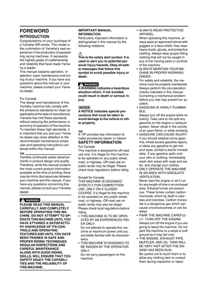 6
6 7
7 8
8 9
9 10
10 11
11 12
12 13
13 14
14 15
15 16
16 17
17 18
18 19
19 20
20 21
21 22
22 23
23 24
24 25
25 26
26 27
27 28
28 29
29 30
30 31
31 32
32 33
33 34
34 35
35 36
36 37
37 38
38 39
39 40
40 41
41 42
42 43
43 44
44 45
45 46
46 47
47 48
48 49
49 50
50 51
51 52
52 53
53 54
54 55
55 56
56 57
57 58
58 59
59 60
60 61
61 62
62 63
63 64
64 65
65 66
66 67
67 68
68 69
69 70
70 71
71 72
72 73
73 74
74 75
75 76
76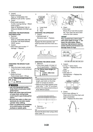 77
77 78
78 79
79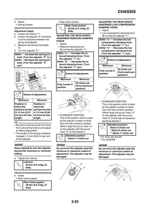 80
80 81
81 82
82 83
83 84
84 85
85 86
86 87
87 88
88 89
89 90
90 91
91 92
92 93
93 94
94 95
95 96
96 97
97 98
98 99
99 100
100 101
101 102
102 103
103 104
104 105
105 106
106 107
107 108
108 109
109 110
110 111
111 112
112 113
113 114
114 115
115 116
116 117
117 118
118 119
119 120
120 121
121 122
122 123
123 124
124 125
125 126
126 127
127 128
128 129
129 130
130 131
131 132
132 133
133 134
134 135
135 136
136 137
137 138
138 139
139 140
140 141
141 142
142 143
143 144
144 145
145 146
146 147
147 148
148 149
149 150
150 151
151 152
152 153
153 154
154 155
155 156
156 157
157 158
158 159
159 160
160 161
161 162
162 163
163 164
164 165
165 166
166 167
167 168
168 169
169 170
170 171
171 172
172 173
173 174
174 175
175 176
176 177
177 178
178 179
179 180
180 181
181 182
182 183
183 184
184 185
185 186
186 187
187 188
188 189
189 190
190 191
191 192
192 193
193 194
194 195
195 196
196 197
197 198
198 199
199 200
200 201
201 202
202 203
203 204
204 205
205 206
206 207
207 208
208 209
209 210
210 211
211 212
212 213
213 214
214 215
215 216
216 217
217 218
218 219
219 220
220 221
221 222
222 223
223 224
224 225
225
Adjusting steps:
a. Turn the adjusting screw \"1\" in di-
rection \"a\" or \"b\".
Direction \"a\" Headlight beam is
r")

CARBURETOR SETTING PARTS
Main jet SizePart
number
(-14943-)
Rich #185 4MX-44
#182 4MX-94
#180 4MX-43
#178 4MX-93
#175 4MX-42
#172 4MX-92
#170 4MX-41
#168 4MX-91
#165 4")