2009 YAMAHA WR 250F ECU
[x] Cancel search: ECUPage 120 of 224

5-24
VALVES AND VALVE SPRINGS
CHECKING THE VALVE SPRINGS
1. Measure:• Valve spring free length "a"Out of specification →Replace.
2. Measure: • Compressed spring force "a"Out of specification →Replace.
b. Installed length
3. Measure: • Spring tilt "a"Out of specification →Replace. CHECKING THE VALVE LIFTERS
1. Inspect:
• Valve lifterScratches/damage →Replace
both lifters and cylinder head.
INSTALLING THE VALVES
1. Apply: • Molybdenum disulfide oilOnto the valve stem and valve
stem seal.
2. Install: •Valve "1"
• Valve spring seat "2"
• Valve stem seal "3"
• Valve spring "4"
• Valve spring retainer "5"To cylinder head.
• Make sure that each valve is in-stalled in its original place, also re-
ferring to the painted color as
follows.
Intake (middle) "a": Orange
Intake (right/left) "b": Green
Exhaust "c": Purple
• Install the valve springs with the larger pitch "d" facing upward.
e. Smaller pitch 3. Install:
• Valve cotter
While compressing the valve spring
with a valve spring compressor "1" in-
stall the valve cotters.
4. To secure the valve cotters onto the valve stem, lightly tap the
valve tip with a piece of wood.
Hitting the valve tip with excessive
force could damage the valve.
5. Install:• Adjusting pad "1"
• Valve lifter "2"
• Apply the molybdenum disulfide oil on the valve stem end.
• Apply the engine oil on the valve lift- ers.
• Valve lifter must turn smoothly
when rotated with a finger.
• Be careful to reinstall valve lifters and pads in their original place.
Free length (valve
spring):
Intake:36.58 mm (1.44 in)
(1.45 in)
Exhaust:
35.58 mm (1.40 in)
(1.44 in)
Compressed spring
force: Intake:103–118 N at 29.13
mm (10.50–12.09 kg at
29.13 mm, 23.15–
26.66 lb at 1.15 in)
Exhaust: 126–144 N at 29.30
mm (12.85–14.68 kg at
29.30 mm, 28.32–
32.37 lb at 1.15 in)
Spring tilt limit: Intake:2.5°/1.6 mm (0.063 in)
Exhaust:
2.5°/1.6 mm (0.063 in)
Valve spring compres-
sor: YM-4019/90890-04019
Page 151 of 224

5-55
ENGINE REMOVAL
HANDLING NOTE
Support the machine securely so
there is no danger of it falling over.
REMOVING THE DRIVE
SPROCKET
1. Remove:• Nut (drive sprocket) "1"
• Lock washer "2"
• Straighten the lock washer tab.
• Loosen the nut while applying the rear brake.
2. Remove:• Drive sprocket "1"
• Drive chain "2"
Remove the drive sprocket together
with the drive chain.
REMOVING THE ENGINE
1. Remove:• Pivot shaft "1"
If the pivot shaft is pulled all the way
out, the swingarm will come loose. If
possible, insert a shaft of similar di-
ameter into the other side of the swin-
garm to support it.
2. Remove:
•Engine "1"From right side.
Make sure that the couplers, hoses
and cables are disconnected.
INSTALLING THE ENGINE
1. Install:•Engine "1"
Install the engine from right side.
• Pivot shaft "2"
• Engine mounting bolt (lower) "3"
• Lower engine bracket "4"
• Bolt (lower engine bracket) "5"
•Patch "6"
• Engine mounting bolt (front) "7"
• Upper engine bracket "8"
• Bolt (upper engine bracket) "9"
• Engine mounting bolt (upper) "10"
• Lower engine guard "11"
• Bolt (lower engine guard) "12"
• Apply the molybdenum disulfide grease on the pivot shaft.
• Install the patch with the claw "a" facing outside the chassis.
INSTALLING THE BRAKE PEDAL
1. Install:• Spring "1"
• Brake pedal "2"
• O-ring "3"
• Bolt (brake pedal) "4"
•Clip "5"
Apply the lithium soap base grease
on the bolt, O-rings and brake pedal
bracket.
INSTALLING THE DRIVE
SPROCKET
1. Install:
• Drive sprocket "1"
• Drive chain "2"
Install the drive sprocket together
with the drive chain.
Pivot shaft: 85 Nm (8.5 m•kg, 61
ft•lb)
Engine mounting bolt
(lower): 53Nm (5.3 m•kg, 38
ft•lb)
Bolt (lower engine brack-
et): 34 Nm (3.4 m•kg, 24
ft•lb)
Engine mounting bolt
(front): 53 Nm (5.3 m•kg, 38
ft•lb)
Bolt (upper engine brack-
et): 34 Nm (3.4 m•kg, 24
ft•lb)
Engine mounting bolt
(upper): 55 Nm (5.5 m•kg, 40
ft•lb)
Bolt (lower engine
guard): 7 Nm (0.7 m•kg, 5.1
ft•lb)
Bolt (brake pedal):
26 Nm (2.6 m•kg, 19
ft•lb)
Page 164 of 224

6-3
FRONT WHEEL AND REAR WHEEL
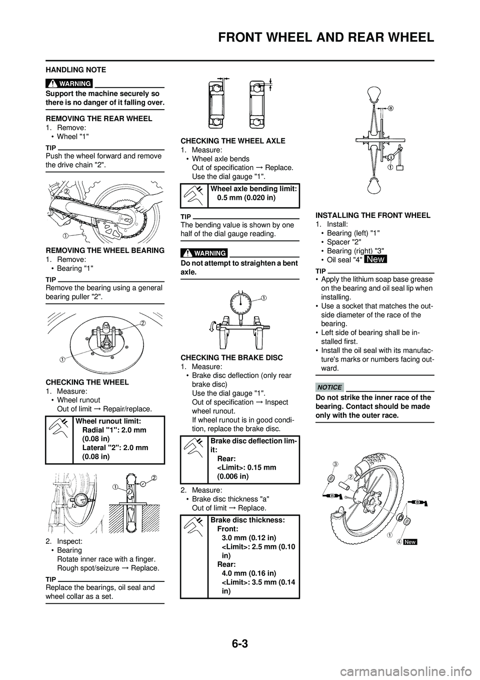
HANDLING NOTE
Support the machine securely so
there is no danger of it falling over.
REMOVING THE REAR WHEEL
1. Remove:• Wheel "1"
Push the wheel forward and remove
the drive chain "2".
REMOVING THE WHEEL BEARING
1. Remove:• Bearing "1"
Remove the bearing using a general
bearing puller "2".
CHECKING THE WHEEL
1. Measure:• Wheel runout
Out of limit → Repair/replace.
2. Inspect: • BearingRotate inner race with a finger.
Rough spot/seizure → Replace.
Replace the bearings, oil seal and
wheel collar as a set.
CHECKING THE WHEEL AXLE
1. Measure:
• Wheel axle bendsOut of specification → Replace.
Use the dial gauge "1".
The bending value is shown by one
half of the dial gauge reading.
Do not attempt to straighten a bent
axle.
CHECKING THE BRAKE DISC
1. Measure: • Brake disc deflection (only rear
brake disc)
Use the dial gauge "1".
Out of specification → Inspect
wheel runout.
If wheel runout is in good condi-
tion, replace the brake disc.
2. Measure: • Brake disc thickness "a"
Out of limit → Replace. INSTALLING THE FRONT WHEEL
1. Install:
• Bearing (left) "1"
•Spacer "2"
• Bearing (right) "3"
•Oil seal "4"
• Apply the lithium soap base grease on the bearing and oil seal lip when
installing.
• Use a socket that matches the out- side diameter of the race of the
bearing.
• Left side of bearing shall be in- stalled first.
• Install the oil seal with its manufac-
ture's marks or numbers facing out-
ward.
Do not strike the inner race of the
bearing. Contact should be made
only with the outer race.
Wheel runout limit: Radial "1": 2.0 mm
(0.08 in)
Lateral "2": 2.0 mm
(0.08 in)
Wheel axle bending limit:0.5 mm (0.020 in)
Brake disc deflection lim-
it: Rear:
(0.006 in)
Brake disc thickness: Front:3.0 mm (0.12 in)
in)
Rear:
4.0 mm (0.16 in)
in)
Page 171 of 224

6-10
FRONT BRAKE AND REAR BRAKE
HANDLING NOTE
Support the machine securely so
there is no danger of it falling over.
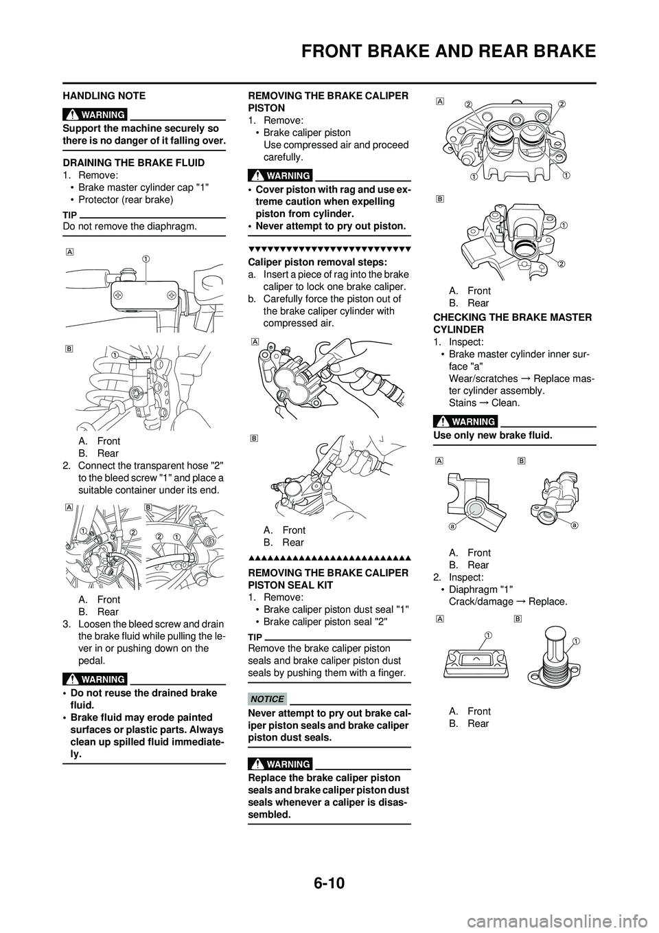
DRAINING THE BRAKE FLUID
1. Remove:• Brake master cylinder cap "1"
• Protector (rear brake)
Do not remove the diaphragm.
A. Front
B. Rear
2. Connect the transparent hose "2" to the bleed screw "1" and place a
suitable container under its end.
A. Front
B. Rear
3. Loosen the bleed screw and drain the brake fluid while pulling the le-
ver in or pushing down on the
pedal.
• Do not reuse the drained brake
fluid.
• Brake fluid may erode painted
surfaces or plastic parts. Always
clean up spilled fluid immediate-
ly.
REMOVING THE BRAKE CALIPER
PISTON
1. Remove:• Brake caliper piston
Use compressed air and proceed
carefully.
• Cover piston with rag and use ex-treme caution when expelling
piston from cylinder.
• Never attempt to pry out piston.
Caliper piston removal steps:
a. Insert a piece of rag into the brake caliper to lock one brake caliper.
b. Carefully force the piston out of the brake caliper cylinder with
compressed air.
A. Front
B. Rear
REMOVING THE BRAKE CALIPER
PISTON SEAL KIT
1. Remove:• Brake caliper piston dust seal "1"
• Brake caliper piston seal "2"
Remove the brake caliper piston
seals and brake caliper piston dust
seals by pushing them with a finger.
Never attempt to pry out brake cal-
iper piston seals and brake caliper
piston dust seals.
Replace the brake caliper piston
seals and brake caliper piston dust
seals whenever a caliper is disas-
sembled.
A. Front
B. Rear
CHECKING THE BRAKE MASTER
CYLINDER
1. Inspect: • Brake master cylinder inner sur-face "a"
Wear/scratches → Replace mas-
ter cylinder assembly.
Stains →Clean.
Use only new brake fluid.
A. Front
B. Rear
2. Inspect: • Diaphragm "1"Crack/damage →Replace.
A. Front
B. Rear
Page 179 of 224

6-18
FRONT FORK
HANDLING NOTE
Support the machine securely so
there is no danger of it falling over.
The front fork requires careful atten-
tion. So it is recommended that the
front fork be maintained at the deal-
ers.
To prevent an accidental explosion
of air, the following instructions
should be observed:
• The front fork with a built-in pis-ton rod has a very sophisticated
internal construction and is par-
ticularly sensitive to foreign ma-
terial. Use enough care not to
allow any foreign material to
come in when the oil is replaced
or when the front fork is disas-
sembled and reassembled.
• Before removing the cap bolts or front forks, be sure to extract the
air from the air chamber com-
pletely.
REMOVING THE FRONT FORK
CAP BOLT
1. Remove:
• Front fork cap bolt "1"From the outer tube.
Before removing the front fork from
the machine, loosen the front fork cap
bolt.
2. Remove:• Front fork cap bolt "1"
Hold the locknut "2" and remove the
front fork cap bolt.
REMOVING THE INNER TUBE
1. Remove:
• Dust seal "1"
• Stopper ring "2"Using slotted-head screwdriver.
Take care not to scratch the inner
tube.
2. Remove:• Inner tube "1"
Oil seal removal steps:
a. Push in slowly "a" the inner tube just before it bottoms out and then
pull it back quickly "b".
b. Repeat this step until the inner tube can be pulled out from the
outer tube.
REMOVING THE DAMPER ROD
1. Remove:
• Base valve "1"
• Damper rod "2"
Use a damper rod holder "3" to lock
the damper rod.
CHECKING THE DAMPER ROD
1. Inspect:• Damper rod "1"Bend/damage →Replace damper
rod.
The front fork with a built-in piston
rod has a very sophisticated inter-
nal construction and is particularly
sensitive to foreign material.
Use enough care not to allow any
foreign material to come in when
the oil is replaced or when the
front fork is disassembled and re-
assembled.
CHECKING THE BASE VALVE
1. Inspect: • Valve assembly "1"Wear/damage →Replace.
• O-ring "2" Damage → Replace.
CHECKING THE FORK SPRING
1. Measure: • Fork spring free length "a"
Out of specification →Replace.
Damper rod holder:
YM-01494/90890-01494
Fork spring free length:460 mm (18.1 in)
in)
Page 190 of 224

6-29
STEERING
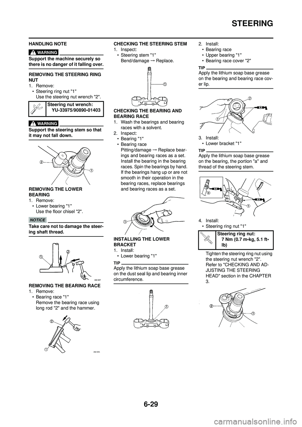
HANDLING NOTE
Support the machine securely so
there is no danger of it falling over.
REMOVING THE STEERING RING
NUT
1. Remove:• Steering ring nut "1"Use the steering nut wrench "2".
Support the steering stem so that
it may not fall down.
REMOVING THE LOWER
BEARING
1. Remove:
• Lower bearing "1"Use the floor chisel "2".
Take care not to damage the steer-
ing shaft thread.
REMOVING THE BEARING RACE
1. Remove:
• Bearing race "1"Remove the bearing race using
long rod "2" and the hammer. CHECKING THE STEERING STEM
1. Inspect:
• Steering stem "1"Bend/damage →Replace.
CHECKING THE BEARING AND
BEARING RACE
1. Wash the bearings and bearing races with a solvent.
2. Inspect: • Bearing "1"
• Bearing race
Pitting/damage →Replace bear-
ings and bearing races as a set.
Install the bearing in the bearing
races. Spin the bearings by hand.
If the bearings hang up or are not
smooth in their operation in the
bearing races, replace bearings
and bearing races as a set.
INSTALLING THE LOWER
BRACKET
1. Install: • Lower bearing "1"
Apply the lithium soap base grease
on the dust seal lip and bearing inner
circumference.
2. Install:• Bearing race
• Upper bearing "1"
• Bearing race cover "2"
Apply the lithium soap base grease
on the bearing and bearing race cov-
er lip.
3. Install:• Lower bracket "1"
Apply the lithium soap base grease
on the bearing, the portion "a" and
thread of the steering stem.
4. Install:• Steering ring nut "1"
Tighten the steering ring nut using
the steering nut wrench "2".
Refer to "CHECKING AND AD-
JUSTING THE STEERING
HEAD" section in the CHAPTER
3.
Steering nut wrench:
YU-33975/90890-01403
Steering ring nut:7 Nm (0.7 m•kg, 5.1 ft•
lb)
Page 194 of 224

6-33
SWINGARM
HANDLING NOTE
Support the machine securely so
there is no danger of it falling over.
REMOVING THE CAP
1. Remove:• Left cap "1"
Remove with a slotted-head screw-
driver inserted under the mark "a" on
the left cap.
REMOVING THE BEARING
1. Remove:• Bearing "1"
Remove the bearing by pressing its
outer race.
CHECKING THE SWINGARM
1. Inspect:
• Bearing "1"
• Bushing "2"Free play exists/unsmooth revolu-
tion/rust →Replace bearing and
bushing as a set.
2. Inspect:
•Oil seal "3"Damage →Replace. CHECKING THE RELAY ARM
1. Inspect:
• Bearing "1"
•Collar "2"Free play exists/unsmooth revolu-
tion/rust → Replace bearing and
collar as a set.
2. Inspect: • Oil seal "3"Damage →Replace.
CHECKING THE CONNECTING
ROD
1. Inspect: • Bearing "1"
•Collar "2"Free play exists/unsmooth revolu-
tion/rust →Replace bearing and
collar as a set.
2. Inspect:
• Oil seal "3"Damage →Replace.
INSTALLING THE BEARING AND
OIL SEAL
1. Install: • Bearing "1"
• Oil seal "2"
To swingarm.
• Apply the molybdenum disulfide grease on the bearing when install-
ing.
• Install the bearing by pressing it on the side having the manufacture's
marks or numbers.
• First install the outer and then the inner bearings to a specified depth
from inside.
2. Install:
• Bearing "1"
• Washer "2"
•Oil seal "3"To relay arm.
• Apply the molybdenum disulfide grease on the bearing when install-
ing.
• Install the bearing by pressing it on the side having the manufacture's
marks or numbers.
• Apply the molybdenum disulfide grease on the washer.
3. Install:• Bearing "1"
•Oil seal "2"To connecting rod.
Installed depth of bear-
ings: Outer "a": Zero mm
(Zero in)
Inner "b": 6.5 mm (0.26
in)
Installed depth of bear-
ings "a":Zero mm (Zero in)
Page 199 of 224

6-38
REAR SHOCK ABSORBER
HANDLING NOTE
• Support the machine securely so there is no danger of it falling
over.
• This rear shock absorber is pro-
vided with a separate type tank
filled with high-pressure nitro-
gen gas. To prevent the danger
of explosion, read and under-
stand the following information
before handling the shock ab-
sorber. The manufacturer can
not be held responsible for prop-
erty damage or personal injury
that may result from improper
handling.
• Never tamper or attempt to dis-assemble the cylinder or the
tank.
• Never throw the rear shock ab-
sorber into an open flame or
other high heat. The rear shock
absorber may explode as a re-
sult of nitrogen gas expansion
and/ or damage to the hose.
• Be careful not to damage any
part of the gas tank. A damaged
gas tank will impair the damp-
ing performance or cause a
malfunction.
• Take care not to scratch the contact surface of the piston
rod with the cylinder; or oil
could leak out.
• Never attempt to remove the plug at the bottom of the nitro-
gen gas tank. It is very danger-
ous to remove the plug.
• When scrapping the rear shock
absorber, follow the instruc-
tions on disposal.
NOTES ON DISPOSAL (YAMAHA
DEALERS ONLY)
Before disposing the rear shock ab-
sorber, be sure to extract the nitrogen
gas from valve "1". Wear eye protec-
tion to prevent eye damage from es-
caping gas and/or metal chips.
To dispose of a damaged or worn-
out rear shock absorber, take the
unit to your Yamaha dealer for this
disposal procedure.
REMOVING THE BEARING
1. Remove:• Stopper ring (upper bearing) "1"
Press in the bearing while pressing its
outer race and remove the stopper
ring.
2. Remove:• Upper bearing "1"
Remove the bearing by pressing its
outer race.
3. Remove:• Lower bearing "1"
Remove the bearing by pressing its
outer race.
CHECKING THE REAR SHOCK
ABSORBER
1. Inspect:• Damper rod "1"
Bends/damage →Replace rear
shock absorber assembly.
• Shock absorber "2"
Oil leaks →Replace rear shock
absorber assembly.
Gas leaks →Replace rear shock
absorber assembly.
• Spring "3" Damage →Replace spring.
Fatigue →Replace spring.
Move spring up and down.
• Spring guide "4"
Wear/damage →Replace spring
guide.
• Bearing "5"
Free play exists/unsmooth revolu-
tion/rust →Replace.
INSTALLING THE BEARING
1. Install: • Upper bearing "1"
Install the bearing parallel until the
stopper ring groove appears by
pressing its outer race.
Do not apply the grease on the
bearing outer race because it will
wear the rear shock absorber sur-
face on which the bearing is press
fitted.