Page 57 of 76

PERIODIC MAINTENANCE AND ADJUSTMENT
6-24
6
EAUM1650
Lubricating the swingarm piv-
ots The swingarm pivots must be lubricat-
ed at the intervals specified in the peri-
odic maintenance and lubrication chart.
EAU23272
Checking the front fork The condition and operation of the front
fork must be checked as follows at the
intervals specified in the periodic main-
tenance and lubrication chart.
To check the condition
Check the inner tubes for scratches,
damage and excessive oil leakage.
To check the operation
1. Place the vehicle on a level sur-
face and hold it in an upright posi-
tion. WARNING! To avoid injury,
securely support the vehicle so
there is no danger of it falling
over.
[EWA10751]
2. While applying the front brake,
push down hard on the handlebars
several times to check if the front
fork compresses and rebounds
smoothly.
NOTICE
ECA10590
If any damage is found or the front
fork does not operate smoothly,
have a Yamaha dealer check or re-pair it.
Recommended lubricant:
Lithium-soap-based grease
U5B681E0.book Page 24 Tuesday, June 17, 2008 5:48 PM
Page 58 of 76

PERIODIC MAINTENANCE AND ADJUSTMENT
6-25
6
EAU23283
Checking the steering Worn or loose steering bearings may
cause danger. Therefore, the operation
of the steering must be checked as fol-
lows at the intervals specified in the pe-
riodic maintenance and lubrication
chart.
1. Place a stand under the engine to
raise the front wheel off the
ground. (See page 6-27 for more
information.) WARNING! To
avoid injury, securely support
the vehicle so there is no danger
of it falling over.
[EWA10751]
2. Hold the lower ends of the front
fork legs and try to move them for-
ward and backward. If any free
play can be felt, have a Yamaha
dealer check or repair the steering.
EAU23290
Checking the wheel bearings The front and rear wheel bearings must
be checked at the intervals specified in
the periodic maintenance and lubrica-
tion chart. If there is play in the wheel
hub or if the wheel does not turn
smoothly, have a Yamaha dealer check
the wheel bearings.
EAU23395
Battery The battery is located behind panel B.
(See page 6-6.)
This model is equipped with a VRLA
(Valve Regulated Lead Acid) battery.
There is no need to check the electro-
lyte or to add distilled water. However,
the battery coupler needs to be
checked and, if necessary, securely
fastened.
WARNING
EWA10760
�
Electrolyte is poisonous and
dangerous since it contains sul-
furic acid, which causes severe
1. Battery coupler
2. Battery band
3. Battery
2
3
1
U5B681E0.book Page 25 Tuesday, June 17, 2008 5:48 PM
Page 59 of 76

PERIODIC MAINTENANCE AND ADJUSTMENT
6-26
6 burns. Avoid any contact with
skin, eyes or clothing and al-
ways shield your eyes when
working near batteries. In case
of contact, administer the fol-
lowing FIRST AID.
EXTERNAL: Flush with plenty
of water.
INTERNAL: Drink large quan-
tities of water or milk and im-
mediately call a physician.
EYES: Flush with water for 15
minutes and seek prompt
medical attention.
�
Batteries produce explosive hy-
drogen gas. Therefore, keep
sparks, flames, cigarettes, etc.,
away from the battery and pro-
vide sufficient ventilation when
charging it in an enclosed
space.
�
KEEP THIS AND ALL BATTER-
IES OUT OF THE REACH OFCHILDREN.To charge the battery
Have a Yamaha dealer charge the bat-
tery as soon as possible if it seems to
have discharged. Keep in mind that the
battery tends to discharge more quickly
if the vehicle is equipped with optional
electrical accessories.
NOTICE
ECA16520
To charge a VRLA (Valve Regulated
Lead Acid) battery, a special (con-
stant-voltage) battery charger is re-
quired. Using a conventional battery
charger will damage the battery. If
you do not have access to a con-
stant-voltage battery charger, have aYamaha dealer charge your battery.
To store the battery
1. If the model will not be used for
more than one month, remove the
battery, fully charge it, and then
place it in a cool, dry place.
NOTICE: When removing the
battery, be sure the key is
turned to “OFF” before discon-
necting the coupler.
[ECA16322]
2. If the battery will be stored for more
than two months, check it at least
once a month and fully charge it if
necessary.
3. Fully charge the battery before in-
stallation.NOTICE
ECA16530
Always keep the battery charged.
Storing a discharged battery cancause permanent battery damage.
U5B681E0.book Page 26 Tuesday, June 17, 2008 5:48 PM
Page 60 of 76

If the fuse is blown, replace it as fol-
lows.
1. Turn the key t")
PERIODIC MAINTENANCE AND ADJUSTMENT
6-27
6
EAU42023
Replacing the fuse The fuse is located inside the battery
coupler. (See page 6-25.)
If the fuse is blown, replace it as fol-
lows.
1. Turn the key to “OFF” and turn off
all electrical circuits.
2. Disconnect the battery coupler.
3. Remove the blown fuse, and then
install a new fuse of the specified
amperage. WARNING! Do not
use a fuse of a higher amperage
rating than recommended to
avoid causing extensive dam-
age to the electrical system and
possibly a fire.
[EWA15131]
4. Connect the battery coupler.
5. Turn the key to “ON”.
6. If the fuse immediately blows
again, have a Yamaha dealer
check the electrical system.
EAU24350
Supporting the motorcycle Since this model is not equipped with a
centerstand, follow these precautions
when removing the front and rear
wheel or performing other maintenance
requiring the motorcycle to stand up-
right. Check that the motorcycle is in a
stable and level position before starting
any maintenance. A strong wooden
box can be placed under the engine for
added stability.
To service the front wheel
1. Stabilize the rear of the motorcycle
by using a motorcycle stand or, if
an additional motorcycle stand is
not available, by placing a jack un-
der the frame in front of the rear
wheel.
2. Raise the front wheel off the
ground by using a motorcycle
stand.
To service the rear wheel
Raise the rear wheel off the ground by
using a motorcycle stand or, if a motor-
cycle stand is not available, by placing
1. Fuse
2. Spare fuse
1
2
Specified fuse:
10.0 A
U5B681E0.book Page 27 Tuesday, June 17, 2008 5:48 PM
Page 61 of 76
PERIODIC MAINTENANCE AND ADJUSTMENT
6-28
6 a jack either under each side of the
frame in front of the rear wheel or under
each side of the swingarm.
EAU24360
Front wheel
EAU41813
To remove the front wheel
WARNING
EWA10821
To avoid injury, securely support the
vehicle so there is no danger of itfalling over.
1. Slide the rubber cover back.
2. Loosen the locknut at the brake le-
ver, and then turn the adjusting
bolt fully in direction (a).
3. Loosen the axle nut.4. Lift the front wheel off the ground
according to the procedure on
page 6-27.
5. Remove the axle nut and washer.
6. Pull the wheel axle out.1. Rubber cover
2. Brake lever free play adjusting bolt
3. Locknut
3
2
(a)
1
1. Axle nut
2. Washer
1. Wheel axle
U5B681E0.book Page 28 Tuesday, June 17, 2008 5:48 PM
Page 62 of 76

PERIODIC MAINTENANCE AND ADJUSTMENT
6-29
67. Remove the brake shoe assembly
from the wheel hub by pulling it
out.
8. Remove the wheel.
EAU41692
To install the front wheel
1. Install the brake shoe assembly
into the wheel hub.
2. Lift the wheel up between the fork
legs.TIPMake sure that the slot in the brake
shoe plate fits over the retainer on thefork leg.3. Insert the wheel axle from the
right-hand side, and then install
the washer and the axle nut.
4. Lower the front wheel so that it is
on the ground.
5. Tighten the axle nut to the speci-
fied torque.
6. Adjust the brake lever free play.
(See page 6-17.)
7. While applying the front brake,
push down hard on the handlebar
several times to check for proper
fork operation.
EAU25080
Rear wheel
EAU41643
To remove the rear wheel
WARNING
EWA10821
To avoid injury, securely support the
vehicle so there is no danger of itfalling over.
1. Disconnect the brake torque rod
from the brake shoe plate by re-
moving the cotter pin, the nut and
the bolt.
1. Brake shoe assembly
1
1. Slot
2. RetainerTightening torque:
Axle nut:
35 Nm (3.5 m·kgf, 25 ft·lbf)
21
1. Brake torque rod
2. Cotter pin
3. Brake torque rod bolt and nut
4. Brake shoe plate
U5B681E0.book Page 29 Tuesday, June 17, 2008 5:48 PM
Page 63 of 76

PERIODIC MAINTENANCE AND ADJUSTMENT
6-30
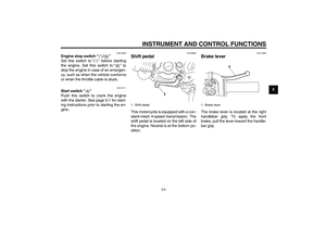
6 2. Remove the brake pedal free play
adjusting nut, and then disconnect
the brake rod at the brake cam-
shaft lever.
3. Loosen the locknut and the drive
chain slack adjusting nut on both
ends of the swingarm.4. Loosen the axle nut.
5. Lift the rear wheel off the ground
according to the procedure on
page 6-27.
6. Remove the axle nut and washer,
and then pull the wheel axle out.
7. Push the wheel forward, and then
remove the drive chain from the
rear sprocket.
TIPThe drive chain does not need to be
disassembled in order to remove andinstall the wheel.
8. Remove the wheel.
EAU41653
To install the rear wheel
1. Install the drive chain onto the rear
sprocket.
2. Insert the wheel axle from the
right-hand side.
3. Lower the rear wheel so that it is
on the ground.
4. Install the brake rod onto the brake
camshaft lever, and then install the
brake pedal free play adjusting nut
onto the brake rod.
1. Brake rod
2. Brake pedal free play adjusting nut
3. Brake camshaft lever
4. Wheel axle
1. Axle nut
2. Washer
3. Drive chain slack adjusting nut
4. Locknut
1
2
4 3
U5B681E0.book Page 30 Tuesday, June 17, 2008 5:48 PM
Page 64 of 76

PERIODIC MAINTENANCE AND ADJUSTMENT
6-31
65. Connect the brake torque rod to
the brake shoe plate by installing
the bolt and nut, and then tighten
the nut to the specified torque.
6. Insert a new cotter pin.
7. Adjust the drive chain slack. (See
page 6-20.)
8. Tighten the axle nut to the speci-
fied torque.
9. Adjust the brake pedal free play.
(See page 6-18.)
EAU25851
Troubleshooting Although Yamaha motorcycles receive
a thorough inspection before shipment
from the factory, trouble may occur dur-
ing operation. Any problem in the fuel,
compression, or ignition systems, for
example, can cause poor starting and
loss of power.
The following troubleshooting chart
represents a quick and easy procedure
for checking these vital systems your-
self. However, should your motorcycle
require any repair, take it to a Yamaha
dealer, whose skilled technicians have
the necessary tools, experience, and
know-how to service the motorcycle
properly.
Use only genuine Yamaha replace-
ment parts. Imitation parts may look like
Yamaha parts, but they are often inferi-
or, have a shorter service life and can
lead to expensive repair bills.
WARNING
EWA15141
When checking the fuel system, do
not smoke, and make sure there are
no open flames or sparks in the ar-
ea, including pilot lights from waterheaters or furnaces. Gasoline or
gasoline vapors can ignite or ex-
plode, causing severe injury or
property damage.
Tightening torque:
Brake torque rod nut:
26 Nm (2.6 m·kgf, 19 ft·lbf)
Tightening torque:
Axle nut:
60 Nm (6.0 m·kgf, 43 ft·lbf)
U5B681E0.book Page 31 Tuesday, June 17, 2008 5:48 PM