2009 YAMAHA SUPERJET fuel cap
[x] Cancel search: fuel capPage 6 of 76

Table of contents
General and important labels ........... 1
Identification numbers .................... 1
Primary Identification (PRI-ID)
number ........................................... 1
Craft Identification Number (CIN) ...... 1
Engine serial number ........................ 1
Important labels .............................. 2
Warning labels ................................... 3
Other labels ....................................... 6
Safety information ............................. 7
Limitations on who may operate
the watercraft .............................. 7
Cruising limitations ......................... 8
Operation requirements ................. 9
Recommended equipment ........... 11
Hazard information ....................... 12
Watercraft characteristics ............. 12
Safe boating rules ........................ 13
Enjoy your watercraft
responsibly ................................ 14
Features and functions ................... 15
Location of main components ...... 15
Operation of controls and other
functions .................................... 17
Hood ................................................ 17
Fuel tank filler cap ........................... 18
Fuel cock knob ................................ 18
Engine stop switch .......................... 19
Engine shut-off switch ..................... 19
Start switch ...................................... 20
Choke knob ..................................... 20
Throttle lever ................................... 20
Cooling water pilot outlet ................. 20
Steering system ............................... 21
Steering pole ................................... 22
Bow rope hole ................................. 22
Stern rope hole ................................ 22
Engine overheat warning system .... 22
Storage pouch ................................. 23
Operation ......................................... 24
Fuel and oil .................................. 24
Fuel ................................................. 24
2-stroke engine oil ........................... 24
Mixing fuel and oil ............................ 24
Filling the fuel tank .......................... 25
Pre-operation checks ................... 26
Pre-operation check list ................... 26
Pre-operation check points .............. 27
Operation ..................................... 32
Engine break-in ............................... 32
Launching the watercraft ................. 32
Starting the engine .......................... 32
Stopping the engine ........................ 34
Leaving the watercraft ..................... 34
Operating your watercraft ............ 35
Getting to know your watercraft ....... 35
Learning to operate your
watercraft ..................................... 35
Operating positions ......................... 36
Starting the watercraft ..................... 36
Boarding and starting in deep
water ............................................ 38
Capsized watercraft ......................... 39
Turning the watercraft ..................... 40
Stopping the watercraft ................... 41
Beaching the watercraft ................... 42
Operating in weeded areas ............. 42
Post-operation care ...................... 42
Transporting ................................. 43
Maintenance and care .................... 45
Storage ........................................ 45
Flushing the cooling system ............ 45
Lubrication ....................................... 46
Battery ............................................. 46
Cleaning the watercraft ................... 47
Maintenance and adjustments ..... 47
Owner’s/operator’s manual and
tool kit ........................................... 47
Periodic maintenance chart ............. 49
Checking the fuel system ................ 51
Checking the jet thrust nozzle
angle ............................................ 51
UF2F71E0.book Page 1 Thursday, April 10, 2008 11:47 AM
Page 22 of 76

Features and functions
15
EJU31010
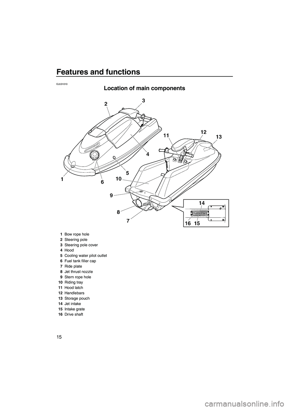
Location of main components
1Bow rope hole
2Steering pole
3Steering pole cover
4Hood
5Cooling water pilot outlet
6Fuel tank filler cap
7Ride plate
8Jet thrust nozzle
9Stern rope hole
10Riding tray
11Hood latch
12Handlebars
13Storage pouch
14Jet intake
15Intake grate
16Drive shaft
UF2F71E0.book Page 15 Thursday, April 10, 2008 11:47 AM
Page 23 of 76

Features and functions
16
1Fire extinguisher container
2Fuel cock knob
3Choke knob
4Clip
5Start switch
6Throttle lever
7Engine shut-off switch
8Engine stop switch
9Engine shut-off cord (lanyard)
10Bow
11Fuel tank
12Battery
13Silencer
14Spark plugs/Spark plug caps
15Muffler
16Water separator
17Fuel filter
18Flushing hose connector
19Electrical box
UF2F71E0.book Page 16 Thursday, April 10, 2008 11:47 AM
Page 25 of 76

Features and functions
18
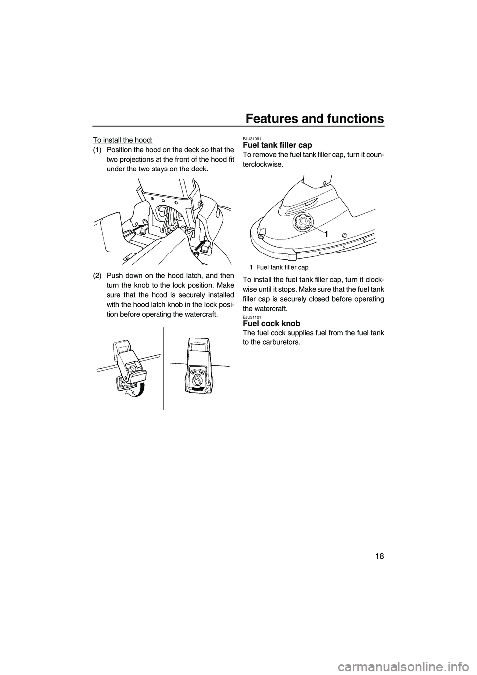
To install the hood:
(1) Position the hood on the deck so that the
two projections at the front of the hood fit
under the two stays on the deck.
(2) Push down on the hood latch, and then
turn the knob to the lock position. Make
sure that the hood is securely installed
with the hood latch knob in the lock posi-
tion before operating the watercraft.
EJU31091Fuel tank filler cap
To remove the fuel tank filler cap, turn it coun-
terclockwise.
To install the fuel tank filler cap, turn it clock-
wise until it stops. Make sure that the fuel tank
filler cap is securely closed before operating
the watercraft.
EJU31121Fuel cock knob
The fuel cock supplies fuel from the fuel tank
to the carburetors.
1Fuel tank filler cap
UF2F71E0.book Page 18 Thursday, April 10, 2008 11:47 AM
Page 32 of 76

Operation
25
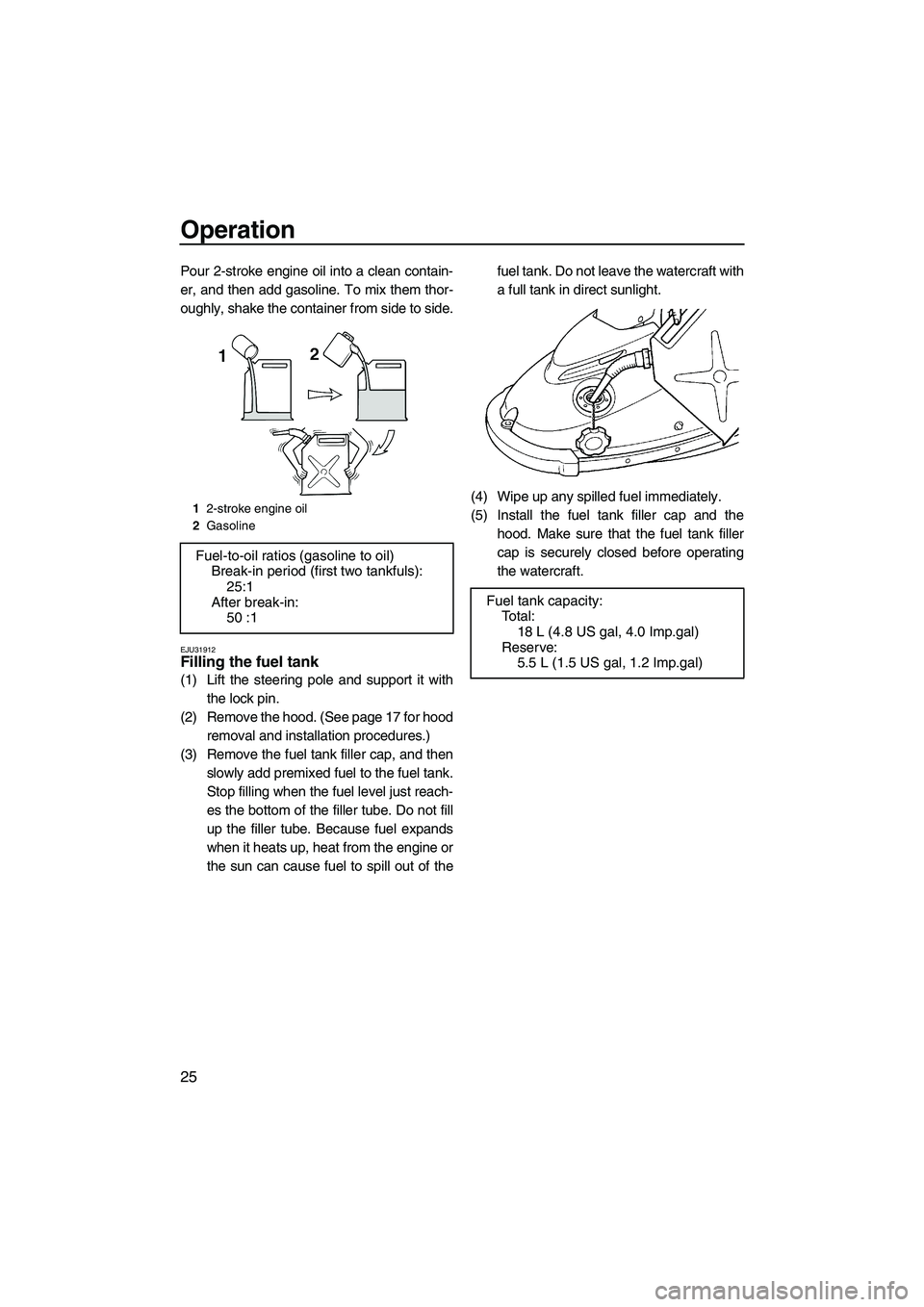
Pour 2-stroke engine oil into a clean contain-
er, and then add gasoline. To mix them thor-
oughly, shake the container from side to side.
EJU31912Filling the fuel tank
(1) Lift the steering pole and support it with
the lock pin.
(2) Remove the hood. (See page 17 for hood
removal and installation procedures.)
(3) Remove the fuel tank filler cap, and then
slowly add premixed fuel to the fuel tank.
Stop filling when the fuel level just reach-
es the bottom of the filler tube. Do not fill
up the filler tube. Because fuel expands
when it heats up, heat from the engine or
the sun can cause fuel to spill out of thefuel tank. Do not leave the watercraft with
a full tank in direct sunlight.
(4) Wipe up any spilled fuel immediately.
(5) Install the fuel tank filler cap and the
hood. Make sure that the fuel tank filler
cap is securely closed before operating
the watercraft.
12-stroke engine oil
2Gasoline
Fuel-to-oil ratios (gasoline to oil)
Break-in period (first two tankfuls):
25:1
After break-in:
50 :1
Fuel tank capacity:
To t a l :
18 L (4.8 US gal, 4.0 Imp.gal)
Reserve:
5.5 L (1.5 US gal, 1.2 Imp.gal)
UF2F71E0.book Page 25 Thursday, April 10, 2008 11:47 AM
Page 34 of 76

Operation
27
EJU32280Pre-operation check points EJU32291Engine compartment
WARNING
EWJ00460
Failure to ventilate the engine compart-
ment could result in a fire or explosion. Do
not start the engine if there is a fuel leak or
a loose electrical connection.
Ventilate the engine compartment before
each use.
To ventilate the engine compartment, lift the
steering pole and support it with the lock pin,
and then remove the hood. (See page 17 for
hood removal and installation procedures.)
Leave the engine compartment open for a few
minutes to allow any fuel vapors to escape.
While the engine compartment is open, check
for loose electrical connections.
EJU32350Hull and deck
Check the hull and deck for cracks and other
damage. If any damage is found, have a
Yamaha dealer repair the watercraft.
EJU32361Fuel system
Make sure that there is sufficient fuel in the
fuel tank before each use.
Also, check the fuel system for leakage,
cracks, and malfunctions. (See page 51 for
check points and correct procedures.)(1) Remove the fuel tank filler cap to release
any pressure that might have built up in
the fuel tank.
(2) Remove the hood. (See page 17 for hood
removal and installation procedures.)
(3) Check the fuel level in the fuel tank and
replenish if necessary. (See page 25 for
filling procedures.)
(4) Install the fuel tank filler cap and the
hood.
EJU32420Water separator
Check the water separator for water. The wa-
ter separator retains any water that may have
entered through the fuel tank breather hose if
the watercraft was capsized. Normally, the
water separator is empty.
If water remains in the water separator, drain
it by removing the drain screw. Place a drain
pan under the water separator to catch the
1Water separator
2Drain screw
UF2F71E0.book Page 27 Thursday, April 10, 2008 11:47 AM
Page 39 of 76

Operation
32
EJU32730
Operation
WARNING
EWJ00510
Before operating your watercraft, become
familiar with all of the controls. Consult a
Yamaha dealer about any control or func-
tion that you do not fully understand. Fail-
ure to understand how the controls work
could cause an accident or prevent you
from avoiding an accident.
EJU32752Engine break-in
NOTICE
ECJ00430
Failure to follow the engine break-in pro-
cedure could result in reduced engine life
or even severe engine damage.
The engine break-in period is essential to al-
low the various components of the engine to
wear and polish themselves to the correct op-
erating clearances. This ensures proper per-
formance and promotes longer component
life.
(1) Fill the fuel tank with fuel in a fuel-to-oil ra-
tio of 25:1.
(2) Launch the watercraft, start the engine,
and then board the watercraft. (See page
32 for engine starting procedures.)
(3) Run the engine at the lowest possible
speed for 5 minutes.
(4) Gradually apply throttle to 3/4 or less.
(5) Operate the watercraft at 3/4 throttle or
less for the first tankful of fuel.
(6) Fill the fuel tank once more with fuel in a
fuel-to-oil ratio of 25:1, and then proceed
with normal operation.
(7) After break-in, fill the fuel tank with fuel in
a fuel-to-oil ratio of 50:1.
EJU32820Launching the watercraft
When launching the watercraft, make sure
that there are no obstacles around you.
After the watercraft is in the water, turn it
around so that the bow faces the direction you
wish to go. Start the engine, and then slowly
move away from the launching area. If there
are waves, someone should make sure that
the watercraft is not pushed into the trailer af-
ter launching the watercraft.
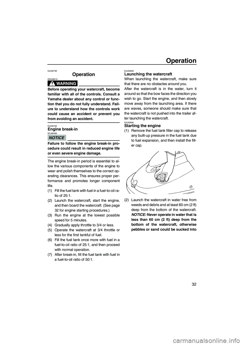
EJU32832Starting the engine
(1) Remove the fuel tank filler cap to release
any built-up pressure in the fuel tank due
to fuel expansion, and then install the fill-
er cap.
(2) Launch the watercraft in water free from
weeds and debris and at least 60 cm (2 ft)
deep from the bottom of the watercraft.
NOTICE: Never operate in water that is
less than 60 cm (2 ft) deep from the
bottom of the watercraft, otherwise
pebbles or sand could be sucked into
UF2F71E0.book Page 32 Thursday, April 10, 2008 11:47 AM
Page 52 of 76

Maintenance and care
45
EJU33480
Storage
WARNING
EWJ00320
Always turn the fuel cock knob to “OFF”
when storing the watercraft, otherwise
fuel could leak out into the engine or en-
gine compartment, which would create a
fire hazard.
Storage for long periods of time, such as win-
ter storage, requires preventive maintenance
to ensure against deterioration. It is advisable
to have the watercraft serviced by a Yamaha
dealer prior to storage. However, the following
procedures can be performed by the owner.
EJU33513Flushing the cooling system
Flushing the cooling system is essential to
prevent it from clogging with salt, sand, or dirt.
(1) Place the watercraft in a horizontal posi-
tion.
(2) Remove the hood. (See page 17 for hood
removal and installation procedures.)
(3) Remove the flushing hose connector
cap, and then insert the garden hoseadapter into the flushing hose connector
and turn it until it is securely connected.
(4) Connect the garden hose adapter to a
water tap using a garden hose.
TIP:
A garden hose is not included.
(5) Start the engine, and then immediately
turn the water supply on until water flows
out continually from the cooling water pi-
lot outlet. NOTICE: Do not run the en-
gine for more than 15 seconds without
supplying water, otherwise the engine
could overheat.
[ECJ01010]
TIP:
If you will be storing the watercraft for a pro-
longed period, such as winter storage, top off
the fuel tank with fresh gasoline and add fuel
stabilizer and conditioner to the fuel tank ac-
cording to the manufacturer’s instruction be-
fore starting the engine.
(6) Run the engine at idling speed for about
3 minutes watching the engine condition.
If the engine stops while flushing, turn the
water supply off immediately and repeat
the above steps. NOTICE: Do not sup-
ply water to the cooling water passag-
es when the engine is not running. The
water could flow back through the
1Garden hose adapter
2Flushing hose connector
3Flushing hose connector cap
UF2F71E0.book Page 45 Thursday, April 10, 2008 11:47 AM