Page 25 of 92

INSTRUMENT AND CONTROL FUNCTIONS
3-11
3
EAU12830
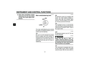
Clutch lever The clutch lever is located at the left
handlebar grip. To disengage the
clutch, pull the lever toward the handle-
bar grip. To engage the clutch, release
the lever. The lever should be pulled
rapidly and released slowly for smooth
clutch operation.
The clutch lever is equipped with a
clutch lever position adjusting dial. To
adjust the distance between the clutch
lever and the handlebar grip, turn the
adjusting dial while holding the lever
pushed away from the handlebar grip.Make sure that the appropriate setting
on the adjusting dial is aligned with the
arrow mark on the clutch lever.
The clutch lever is equipped with a
clutch switch, which is part of the igni-
tion circuit cut-off system. (See page
3-23.)
EAU12870
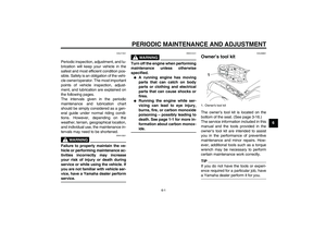
Shift pedal The shift pedal is located on the left
side of the engine and is used in com-
bination with the clutch lever when
shifting the gears of the 5-speed con-
stant-mesh transmission equipped on
this motorcycle.
1. Clutch lever
2. Arrow mark
3. Clutch lever position adjusting dial
4. Distance between clutch lever and handlebar
grip
1. Shift pedal
U5YUE5E0.book Page 11 Tuesday, March 17, 2009 9:02 AM
Page 26 of 92
INSTRUMENT AND CONTROL FUNCTIONS
3-12
3
EAU33851
Brake lever The brake lever is located at the right
handlebar grip. To apply the front
brake, pull the lever toward the handle-
bar grip.
The brake lever is equipped with a
brake lever position adjusting knob. To
adjust the distance between the brake
lever and the handlebar grip, turn the
adjusting knob while holding the lever
pushed away from the handlebar grip.
When the desired position is obtained,be sure to set it by aligning a groove on
the adjusting knob with the“” mark
on the brake lever.
EAU12941
Brake pedal The brake pedal is on the right side of
the motorcycle. To apply the rear
brake, press down on the brake pedal.
1. Brake lever
2. Brake lever position adjusting knob
3. Distance between brake lever and handlebar
grip
4.“” mark
1. Brake pedal
U5YUE5E0.book Page 12 Tuesday, March 17, 2009 9:02 AM
Page 27 of 92

INSTRUMENT AND CONTROL FUNCTIONS
3-13
3
EAU13074
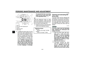
Fuel tank cap To open the fuel tank cap
Open the fuel tank cap lock cover, in-
sert the key into the lock, and then turn
it 1/4 turn clockwise. The lock will be re-
leased and the fuel tank cap can be
opened.
To close the fuel tank cap
1. Push the fuel tank cap into position
with the key inserted in the lock.
2. Turn the key counterclockwise to
the original position, remove it, and
then close the lock cover.
TIPThe fuel tank cap cannot be closed un-
less the key is in the lock. In addition,
the key cannot be removed if the cap is
not properly closed and locked.
WARNING
EWA11091
Make sure that the fuel tank cap is
properly closed after filling fuel.
Leaking fuel is a fire hazard.
EAU13221
Fuel Make sure there is sufficient gasoline in
the tank.
WARNING
EWA10881
Gasoline and gasoline vapors are
extremely flammable. To avoid fires
and explosions and to reduce the
risk of injury when refueling, follow
these instructions.1. Before refueling, turn off the en-
gine and be sure that no one is sit-
ting on the vehicle. Never refuel
while smoking, or while in the vi-
cinity of sparks, open flames, or
other sources of ignition such as
the pilot lights of water heaters and
clothes dryers.
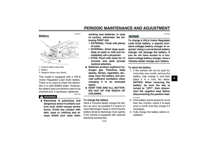
2. Do not overfill the fuel tank. When
refueling, be sure to insert the
pump nozzle into the fuel tank filler
hole. Stop filling when the fuel
reaches the bottom of the filler
tube. Because fuel expands when
it heats up, heat from the engine or
the sun can cause fuel to spill out
of the fuel tank.
1. Fuel tank cap lock cover
2. Unlock.
U5YUE5E0.book Page 13 Tuesday, March 17, 2009 9:02 AM
Page 28 of 92

INSTRUMENT AND CONTROL FUNCTIONS
3-14
3
3. Wipe up any spilled fuel immedi-
ately. NOTICE: Immediately wipe
off spilled fuel with a clean, dry,
soft cloth, since fuel may deteri-
orate painted surfaces or plastic
parts.
[ECA10071]
4. Be sure to securely close the fuel
tank cap.
WARNING
EWA15151
Gasoline is poisonous and can
cause injury or death. Handle gaso-
line with care. Never siphon gaso-
line by mouth. If you should swallow
some gasoline or inhale a lot of gas-
oline vapor, or get some gasoline in
your eyes, see your doctor immedi-ately. If gasoline spills on your skin,
wash with soap and water. If gaso-
line spills on your clothing, change
your clothes.
EAU33501
NOTICE
ECA11400
Use only unleaded gasoline. The use
of leaded gasoline will cause severe
damage to internal engine parts,
such as the valves and piston rings,
as well as to the exhaust system.Your Yamaha engine has been de-
signed to use regular unleaded gaso-
line with a research octane number of
91 or higher. If knocking (or pinging) oc-
curs, use a gasoline of a different brandor premium unleaded fuel. Use of un-
leaded fuel will extend spark plug life
and reduce maintenance costs.
1. Fuel tank filler tube
2. Fuel level
Recommended fuel:
REGULAR UNLEADED GASOLINE
ONLY
Fuel tank capacity:
15.0 L (3.96 US gal, 3.30 Imp.gal)
Fuel reserve amount (when the fuel
level warning light comes on):
3.0 L (0.79 US gal, 0.66 Imp.gal)
U5YUE5E0.book Page 14 Tuesday, March 17, 2009 9:02 AM
Page 29 of 92

INSTRUMENT AND CONTROL FUNCTIONS
3-15
3
EAU34072
Fuel tank breather/overflow
hose Before operating the motorcycle:�
Check the fuel tank breather/over-
flow hose connection.
�
Check the fuel tank breather/over-
flow hose for cracks or damage,
and replace it if damaged.
�
Make sure that the end of the fuel
tank breather/overflow hose is not
blocked, and clean it if necessary.
�
Make sure that the end of the fuel
tank breather/overflow hose is po-
sitioned outside of the cowling.
EAU13445
Catalytic converters This vehicle is equipped with catalytic
converters in the exhaust system.
WARNING
EWA10862
The exhaust system is hot after op-
eration. To prevent a fire hazard or
burns:�
Do not park the vehicle near
possible fire hazards such as
grass or other materials that
easily burn.
�
Park the vehicle in a place
where pedestrians or children
are not likely to touch the hot
exhaust system.
�
Make sure that the exhaust sys-
tem has cooled down before do-
ing any maintenance work.
�
Do not allow the engine to idle
more than a few minutes. Long
idling can cause a build-up of
heat.
NOTICE
ECA10701
Use only unleaded gasoline. The use
of leaded gasoline will cause unre-
pairable damage to the catalytic
converter.
1. Fuel tank breather/overflow hose
2. Cowling
U5YUE5E0.book Page 15 Tuesday, March 17, 2009 9:02 AM
Page 30 of 92

INSTRUMENT AND CONTROL FUNCTIONS
3-16
3
EAU36692
Seat To remove the seat
1. Insert the key into the seat lock,
and then turn it clockwise.
2. Pull the seat off.
To install the seat
1. Insert the projections into the seat
holders as shown.2. Push the center of the seat down
to lock it in place.
3. Remove the key.
TIPMake sure that the seat is properly se-
cured before riding.
EAU48091
Adjusting the front fork
WARNING
EWA10180
Always adjust both fork legs equal-
ly, otherwise poor handling and loss
of stability may result.This front fork is equipped with spring
preload adjusting bolts, rebound damp-
ing force adjusting bolts and compres-
sion damping force adjusting bolts.NOTICE
ECA10101
To avoid damaging the mechanism,
do not attempt to turn beyond the
maximum or minimum settings.Spring preload
To make any adjustment of the spring
preload, the adjuster has to be set to
the standard setting first.
To set the standard setting, start by
turning the adjusting bolt on each fork
leg in direction (a) until it stops, then
check the alignment mark position.
a. If the alignment mark on the ad-
justing bolt is positioned past the
alignment mark on the front fork
1. Seat lock
2. Unlock.
1. Seat holder
2. Projection
U5YUE5E0.book Page 16 Tuesday, March 17, 2009 9:02 AM
Page 31 of 92
INSTRUMENT AND CONTROL FUNCTIONS
3-17
3 cap as shown in illustration “A”,
turn the adjusting bolt in direction
(b) until the alignment marks
match.
To set the standard setting, turn
the adjusting bolt 7 complete turns
in direction (b), making sure the
alignment marks match.b. If the alignment mark on the ad-
justing bolt is positioned before the
alignment mark on the front fork
cap as shown in illustration “B”,
turn the adjusting bolt in direction
(b) until the alignment marks
match.To set the standard setting, turn
the adjusting bolt 6 complete turns
in direction (b), making sure the
alignment marks match.
1. Spring preload adjusting bolt
2. Alignment marks
21
(b)
(a)
È
1. Spring preload adjusting bolt
2. Alignment marks
1
(b)
(a) 2
1. Spring preload adjusting bolt
2. Alignment marks
1. Spring preload adjusting bolt
2. Alignment marks
1
(b)
(a) 2
É
1
(b)
(a) 2
U5YUE5E0.book Page 17 Tuesday, March 17, 2009 9:02 AM
Page 32 of 92
 from the
standard setting, making sure to
turn the bolt compl")
INSTRUMENT AND CONTROL FUNCTIONS
3-18
3To increase the spring preload and
thereby hardening it, turn the ad-
justing bolt in direction (a) from the
standard setting, making sure to
turn the bolt complete turns so that
the alignment marks match.
To decrease the spring preload
and thereby softening it, turn the
adjusting bolt in direction (b) from
the standard setting, making sure
to turn the bolt complete turns so
that the alignment marks match.
TIPDue to small differences in production,
the positions of the alignment marks on
the front fork caps may not exactly
match the illustrations.
Rebound damping force
To increase the rebound damping force
and thereby harden the rebound damp-
ing, turn the adjusting bolt on each fork
leg in direction (a). To decrease the re-
bound damping force and thereby soft-
en the rebound damping, turn the
adjusting bolt on each fork leg in direc-
tion (b).Compression damping force
To increase the compression damping
force and thereby harden the compres-
sion damping, turn the adjusting bolt on
each fork leg in direction (a). To de-
crease the compression damping force
and thereby soften the compression
damping, turn the adjusting bolt on
each fork leg in direction (b).
Spring preload setting:
Minimum (soft):
7 complete turns in direction (b)
from the standard setting
Standard:
See explanations above.
Maximum (hard):
6 complete turns in direction (a)
from the standard setting
1. Rebound damping force adjusting boltRebound damping setting:
Minimum (soft):
17 click(s) in direction (b)*
Standard:
10 click(s) in direction (b)*
Maximum (hard):
1 click(s) in direction (b)*
* With the adjusting bolt fully turned in
direction (a)1
(b)
(a)
1. Compression damping force adjusting boltCompression damping setting:
Minimum (soft):
20 click(s) in direction (b)*
Standard:
10 click(s) in direction (b)*
Maximum (hard):
1 click(s) in direction (b)*
* With the adjusting bolt fully turned in
direction (a)
(b)(a)
1
U5YUE5E0.book Page 18 Tuesday, March 17, 2009 9:02 AM


 until the alignment marks
match.
To set the standard setting, turn
the adjusting")