2009 YAMAHA GIGGLE50 air filter
[x] Cancel search: air filterPage 6 of 74

1
2
3
4
5
6
7
8
9
EAU10210
TABLE OF CONTENTSSAFETY INFORMATION .................... 1-1
Further safe-riding points ................ 1-5
DESCRIPTION ................................... 2-1
Left view .......................................... 2-1
Right view ........................................ 2-2
Controls and instruments ................ 2-3
INSTRUMENT AND CONTROL FUNC-
TIONS................................................. 3-1
Main switch/steering lock ................ 3-1
Keyhole cover ................................. 3-2
Indicator and warning lights ............ 3-3
Speedometer unit............................ 3-4
Fuel gauge ...................................... 3-5
Handlebar switches........................ 3-5
Front brake lever ............................. 3-6
Rear brake lever ............................. 3-7
Fuel tank cap ................................... 3-7
Fuel................................................. 3-8
Catalytic converters ......................... 3-9
Kickstarter......................................3-10
Seat...............................................3-10
Helmet holder................................3-10
Storage compartment ....................3-11
Luggage hook...............................3-12
FOR YOUR SAFETY - PRE-OPERATION
CHECKS............................................ 4-1
Pre-operation check list .................. 4-2OPERATION AND IMPORTANT RIDING
POINTS............................................... 5-1
Starting the engine .......................... 5-1
Starting off ....................................... 5-2
Acceleration and deceleration........ 5-2
Braking............................................ 5-2
Tips for reducing fuel consumption . 5-3
Engine break-in............................... 5-3
Parking............................................ 5-4
PERIODIC MAINTENANCE AND
ADJUSTMENT................................... 6-1
Periodic maintenance and lubrication
chart............................................. 6-2
Removing and installing panels ..... 6-5
Checking the spark plug ................. 6-6
Engine oil........................................ 6-7
Final transmission oil ...................... 6-9
Coolant..........................................6-10
Replacing the air filter element .....6-11
Checking the throttle cable free
play............................................6-12
Valve clearance.............................6-12
Tires...............................................6-12
Cast wheels ...................................6-14
Adjusting the front and rear brake lever
free play .....................................6-14
Checking the front and rear brake
shoes.........................................6-15Checking and lubricating the throttle
grip and cable ............................6-16
Lubricating the front and rear brake
levers.........................................6-16
Checking and lubricating the
centerstand................................6-17
Checking the front fork ..................6-17
Checking the steering ...................6-18
Checking the wheel bearings .......6-18
Battery ...........................................6-19
Replacing the fuse ........................6-20
Replacing the headlight bulb ........6-21
Replacing the tail/brake light
bulb............................................6-22
Replacing a turn signal light
bulb............................................6-22
Troubleshooting............................6-23
Troubleshooting charts.................6-24
SCOOTER CARE AND STORAGE .... 7-1
Matte color caution .......................... 7-1
Care................................................. 7-1
Storage............................................ 7-4
SPECIFICATIONS.............................. 8-1
CONSUMER INFORMATION ............. 9-1
Identification numbers..................... 9-1
Page 14 of 74

2-14
1
2
3
4
5
6
7
8
9
EAU10401
DESCRIPTION
EAU10401
DESCRIPTION
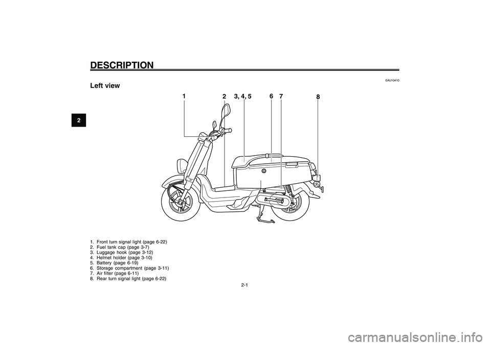
2-1
EAU10410
Left view1. Front turn signal light (page 6-22)
2. Fuel tank cap (page 3-7)
3. Luggage hook (page 3-12)
4. Helmet holder (page 3-10)
5. Battery (page 6-19)
6. Storage compartment (page 3-11)
7. Air filter (page 6-11)
8. Rear turn signal light (page 6-22)Part locations
1
23, 4, 56
8
7
Page 36 of 74

6-36
1
2
3
4
5
6
7
8
9
EAU1722A
PERIODIC MAINTENANCE AND ADJUSTMENT
EAU1722A
PERIODIC MAINTENANCE AND ADJUSTMENT
6-1
EAU17281
Periodic inspection, adjustment, and lu-
brication will keep your vehicle in the
safest and most efficient condition pos-
sible. Safety is an obligation of the ve-
hicle owner/operator. The most important
points of vehicle inspection, adjustment,
and lubrication are explained on the fol-
lowing pages.
The intervals given in the periodic main-
tenance and lubrication chart should be
simply considered as a general guide
under normal riding conditions. However,
depending on the weather, terrain, geo-
graphical location, and individual use,
the maintenance intervals may need to
be shortened.
EWA10321
WARNING
Failure to properly maintain the ve-
hicle or performing maintenance ac-
tivities incorrectly may increase your
risk of injury or death during service
or while using the vehicle. If you are
not familiar with vehicle service, have
a Yamaha dealer perform service.
EWA15121
WARNING
Turn off the engine when performing
maintenance unless otherwise speci-
fied.● ●● ●
●
A running engine has moving
parts that can catch on body parts
or clothing and electrical parts
that can cause shocks or fires.
● ●● ●
●
Running the engine while servic-
ing can lead to eye injury, burns,
fire, or carbon monoxide poison-
ing - possibly leading to death.
See page 1-1 for more informa-
tion about carbon monoxide.
EWA10330
WARNING
This scooter is designed for use on
paved roads only. If this scooter is
operated in abnormally dusty, muddy
or wet conditions, the air filter ele-
ment should be cleaned or replaced
more frequently, otherwise rapid en-
gine wear may result. Consult aYamaha dealer for proper mainte-
nance intervals.
Page 37 of 74

6-37
1
2
3
4
5
6
7
8
9
EAU1722A
PERIODIC MAINTENANCE AND ADJUSTMENT
6-2
Periodic maintenance and lubrication chart
EAU17715
Periodic maintenance and lubrication chartTIP● ●● ●
●
The annual checks must be performed every year, except if a kilometer-based maintenance, or for the UK, a
mileage-based maintenance, is performed instead.
●
From 30000 km (17500 mi), repeat the maintenance intervals starting from 6000 km (3500 mi).
●
Items marked with an asterisk should be performed by a Yamaha dealer as they require special tools, data and technical
skills.
NO. ITEM CHECK OR MAINTENANCE JOBODOMETER READING
ANNUAL
CHECK
1000 km
(600 mi)6000 km
(3500 mi)12000 km
(7000 mi)18000 km
(10500 mi)24000 km
(14000 mi)
1
*Fuel line• Check fuel hoses and vacuum hose for cracks or
damage.�—�—�—�— �—
2 Spark plug• Check condition.
• Clean and regap.�—�—
• Replace.�—�—
3*Valves• Check and adjust valve clearance when engine is cold.�—�—�—�—
4*Air filter element• Replace.�—�—�—�— �—
5*Front brake• Check operation and adjust brake lever free play.�—�— �— �— �— �—
• Replace brake shoes. Whenever worn to the limit
6*Rear brake• Check operation and adjust brake lever free play.�—�—�—�—�— �—
• Replace brake shoes. Whenever worn to the limit
7*Wheels• Check runout and for damage.�—�—�—�—
8*Tires• Check tread depth and for damage.
• Replace if necessary.
• Check air pressure.
• Correct if necessary.�—�—�—�— �—
9*Wheel bearings• Check bearing for looseness or damage.�—�—�—�—
Page 46 of 74

6-46
1
2
3
4
5
6
7
8
9
EAU1722A
PERIODIC MAINTENANCE AND ADJUSTMENT
6-11
ZAUM00**
1
1. Coolant reservoir cap3. If the coolant is at or below the mini-
mum level mark, remove panel B
and the reservoir cap. (See page 6-
5.) WARNING! Remove only the
coolant reservoir cap. Never at-
tempt to remove the radiator cap
when the engine is hot.
[EWA15161]
4. Add coolant or distilled water to
raise the coolant to the maximum
level mark, and install the coolant
reservoir cap and the panel.
NOTICE:
If coolant is not avail-
able, use distilled water or soft
tap water instead. Do not use hard
water or salt water since it isharmful to the engine. If water
has been used instead of cool-
ant, replace it with coolant as
soon as possible, otherwise the
cooling system will not be pro-
tected against frost and corro-
sion. If water has been added to
the coolant, have a Yamaha
dealer check the antifreeze con-
tent of the coolant as soon as
possible, otherwise the effective-
ness of the coolant will be
reduced.
[ECA10472]
Coolant reservoir capacity:
0.26 L (0.27 US qt, 0.23 Imp.qt)
EAUT1990
Replacing the air filter ele-
mentThe air filter element must be replaced
and the check hoses must be cleaned
at the intervals specified in the periodic
maintenance and lubrication chart. Have
a Yamaha dealer replace the air filter el-
ement. Air filter element, replacing
Page 66 of 74

8-66
1
2
3
4
5
6
7
8
9
EAU26320
SPECIFICATIONS
8-1
EAU26320
SPECIFICATIONSSpecifications
1915 mm (75.4 in)
Overall width
695 mm (27.4 in)
Overall height
1040 mm (40.9 in)
Seat height
750 mm (29.5 in)
Wheelbase
1280 mm (50.4 in)
Ground clearance
115 mm (4.53 in)
Minimum turning radius
2000 mm (78.7 in)WeightWith oil and fuel
93.0 kg (205 lb)EngineEngine type
Liquid cooled 4-stroke, SOHC
Cylinder arrangement
Forward-inclined single cylinder
Displacement
49.0 cm
3
Bore x stroke
38.0 x 43.6 mm (1.50 x 1.72 in)
Compression ratio
12.00 :1
Starting system
Electric starter and kickstarter
Lubrication system
Wet sump
Engine oilType
SAE 10W-40
-10 0 10 20 30
40 -20
50
�C
SAE 10W-30
SAE 10W-40
SAE 15W-40SAE 20W-40SAE 20W-50
Recommended engine oil grade
API service SG type or higher, JASO
standard MA
Periodic oil change
0.78 L (0.82 US qt, 0.69 Imp.qt)Final transmission oilType
SAE 10W-30 type SE motor oil
Quantity
0.10 L (0.11 US qt, 0.09 Imp.qt)Cooling systemCoolant reservoir capacity (up to the
maximum level mark)
0.26 L (0.27 US qt, 0.23 Imp.qt)
Radiator capacity (including all routes)
0.50 L (0.53 US qt, 0.44 Imp.qt)Air filterAir filter element
Wet elementFuelRecommended fuel
Regular unleaded gasoline onlyFuel tank capacity
4.5 L (1.19 US gal, 0.99 Imp.gal)
Throttle bodyType/quantity
3B31 00(SE AC19-1) / 1
Manufacturer
MIKUNISpark plug (s)Manufacturer/mode
NGK/CR7E
Spark plug gap
0.7-0.8 mm (0.028-0.031 in)ClutchClutch type
Dry, centrifugal automaticTransmissionPrimary reduction system
Helical gear
Primary reduction ratio
50/13 (3.846)
Secondary reduction system
Helical gear
Secondary reduction ratio
43/12 (3.583)
Transmission type
V-belt automatic
Operation
Centrifugal automatic typeChassisFrame type
Steel tube backbone
Caster angle
26.00 degree
Page 70 of 74

1
2
3
4
5
6
7
8
9
INDEXAAcceleration and deceleration.................. 5-2
Air filter element, replacing .....................6-11BBattery.....................................................6-19
Brake lever, front ...................................... 3-6
Brake lever, rear....................................... 3-7
Brake levers, lubricating.........................6-16
Brake shoes, checking ..........................6-15
Braking...................................................... 5-2CCare.......................................................... 7-1
Catalytic converters................................. 3-9
Centerstand, checking and lubricating ..6-17
Coolant....................................................6-10
Coolant temperature warning light ........... 3-3DDimmer switch.......................................... 3-6EEngine break-in ......................................... 5-3
Engine oil ................................................... 6-7
Engine trouble warning light ..................... 3-4FFinal transmission oil................................ 6-9
Front and rear brake lever free play,
adjusting...............................................6-14
Front fork, checking...............................6-17
Fuel........................................................... 3-8
Fuel consumption, tips for reducing ........ 5-3
Fuel gauge ................................................ 3-5
Fuel tank cap ............................................ 3-7
Fuse, replacing.......................................6-20
HHandlebar switches.................................. 3-5
Headlight bulb, replacing........................6-21
Helmet holder..........................................3-10
High beam indicator light .......................... 3-3
Horn switch............................................... 3-6IIdentification numbers.............................. 9-1
Indicator and warning lights ..................... 3-3KKey identification number......................... 9-1
Keyhole cover........................................... 3-2
Kickstarter..............................................3-10LLuggage hook .........................................3-12MMain switch/steering lock......................... 3-1
Matte color, caution .................................. 7-1
Model label................................................ 9-2PPanels, removing and installing................ 6-5
Parking...................................................... 5-4
Part locations............................................ 2-1
Periodic maintenance and lubrication
chart ....................................................... 6-2
Pre-operation check list........................... 4-2SSafe-riding points...................................... 1-5
Safety information..................................... 1-1
Seat .........................................................3-10
Spark plug, checking................................ 6-6
Specifications............................................ 8-1Speedometer unit..................................... 3-4
Start switch............................................... 3-6
Starting off ................................................. 5-2
Starting the engine.................................... 5-1
Steering, checking..................................6-18
Storage..................................................... 7-4
Storage compartment.............................3-11
TTail/brake light bulb, replacing ................6-22
Throttle cable free play, checking ..........6-12
Throttle grip and cable, checking and
lubricating.............................................6-16
Tires........................................................6-12
Troubleshooting......................................6-23
Troubleshooting charts...........................6-24
Turn signal indicator light.......................... 3-3
Turn signal light bulb, replacing ..............6-22
Turn signal switch ..................................... 3-6VValve clearance......................................6-12
Vehicle identification number .................... 9-1WWheel bearings, checking ......................6-18
Wheels....................................................6-14