2009 YAMAHA FX HO CRUISER start stop button
[x] Cancel search: start stop buttonPage 42 of 106
Features and functions
35
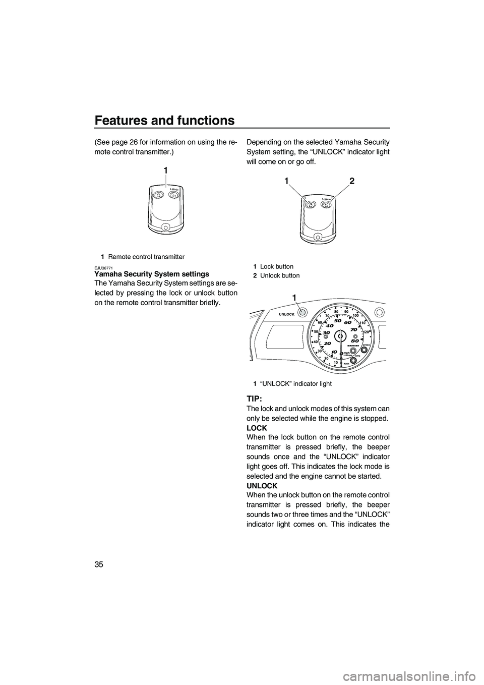
(See page 26 for information on using the re-
mote control transmitter.)
EJU36771Yamaha Security System settings
The Yamaha Security System settings are se-
lected by pressing the lock or unlock button
on the remote control transmitter briefly.Depending on the selected Yamaha Security
System setting, the “UNLOCK” indicator light
will come on or go off.
TIP:
The lock and unlock modes of this system can
only be selected while the engine is stopped.
LOCK
When the lock button on the remote control
transmitter is pressed briefly, the beeper
sounds once and the “UNLOCK” indicator
light goes off. This indicates the lock mode is
selected and the engine cannot be started.
UNLOCK
When the unlock button on the remote control
transmitter is pressed briefly, the beeper
sounds two or three times and the “UNLOCK”
indicator light comes on. This indicates the
1Remote control transmitter
1Lock button
2Unlock button
1“UNLOCK” indicator light
UF2H70E0.book Page 35 Thursday, January 15, 2009 10:49 AM
Page 43 of 106
Features and functions
36
unlock mode is selected and the engine can
be started.
TIP:
The beeper sounds two times for the normal
mode or three times for the low-RPM mode.
(See the items in “Selecting the operation
mode” for operation mode information.)
If neither the start switch nor the remote con-
trol transmitter is operated within 25 seconds
after the unlock button is pressed to select the
unlock mode, the multifunction information
center will turn off and enter a standby state.
If the multifunction information center is in the
standby state, start the engine to return the
display and the indicator lights to their state
before the center turned off.
EJU36781Selecting the operation mode
There are two operation modes in the unlock
mode of the Yamaha Security System: the
normal mode and the low-RPM mode. The
normal mode and low-RPM mode can only be
selected when the engine is stopped in the
unlock mode. Press the unlock button on the
remote control transmitter for more than 4
seconds to switch between the normal mode
and the low-RPM mode.
Normal mode
The watercraft can be ridden normally in this
mode.
If the beeper sounds two times, the normal
mode is activated.Low-RPM mode
Maximum engine speed (r/min) in this mode is
limited to approximately 70% of the maximum
engine speed in the normal mode.
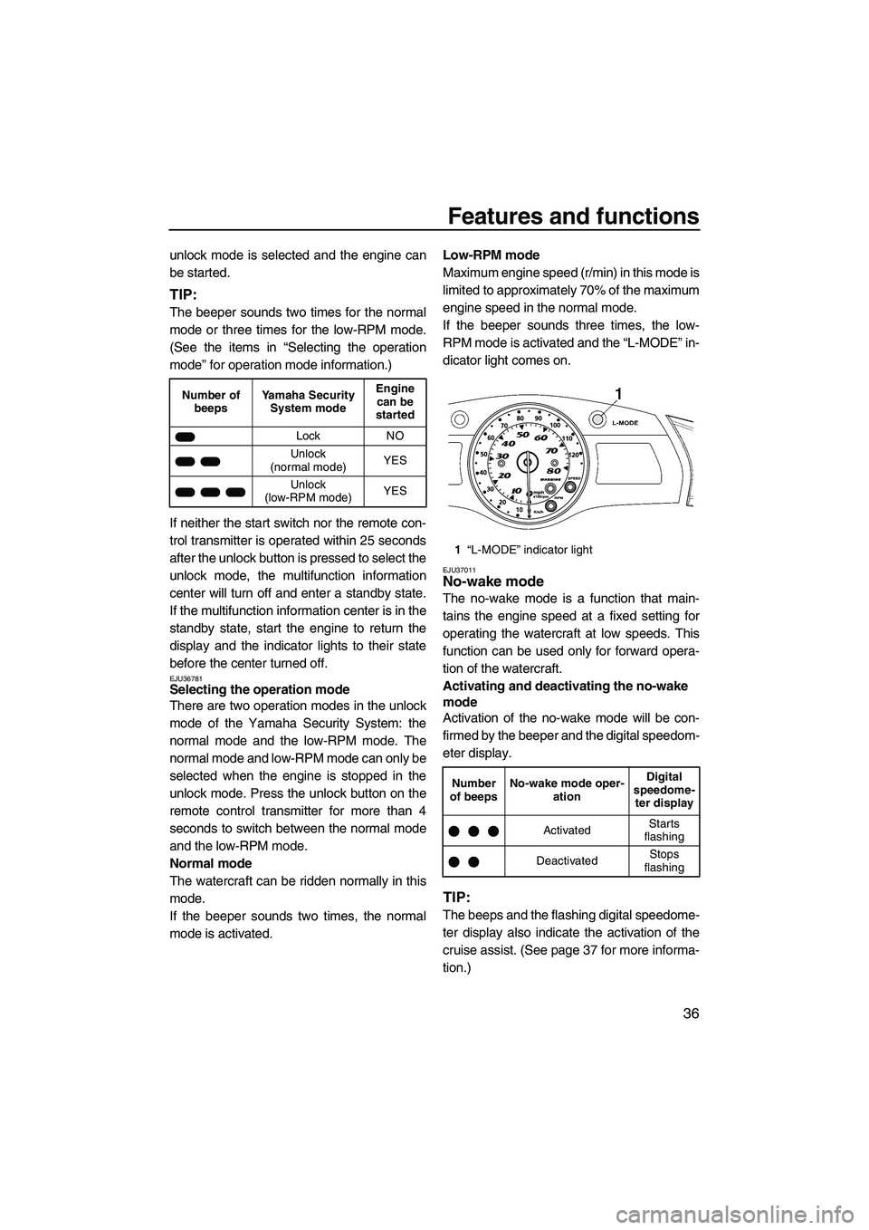
If the beeper sounds three times, the low-
RPM mode is activated and the “L-MODE” in-
dicator light comes on.
EJU37011No-wake mode
The no-wake mode is a function that main-
tains the engine speed at a fixed setting for
operating the watercraft at low speeds. This
function can be used only for forward opera-
tion of the watercraft.
Activating and deactivating the no-wake
mode
Activation of the no-wake mode will be con-
firmed by the beeper and the digital speedom-
eter display.
TIP:
The beeps and the flashing digital speedome-
ter display also indicate the activation of the
cruise assist. (See page 37 for more informa-
tion.)
Number of
beepsYamaha Security
System modeEngine
can be
started
Lock NO
Unlock
(normal mode)YES
Unlock
(low-RPM mode)YES
1“L-MODE” indicator light
Number
of beepsNo-wake mode oper-
ationDigital
speedome-
ter display
ActivatedStarts
flashing
DeactivatedStops
flashing
UF2H70E0.book Page 36 Thursday, January 15, 2009 10:49 AM
Page 47 of 106
Features and functions
40
When the multifunction information center
starts operating, the analog speedometer/ta-
chometer makes one sweep, all displays light
up for 2 seconds, and then the meter starts to
operate normally.
The multifunction information center will con-
tinue to operate for 25 seconds after the en-
gine stops.
EJU34930Analog speedometer/tachometer and indi-
cator lights
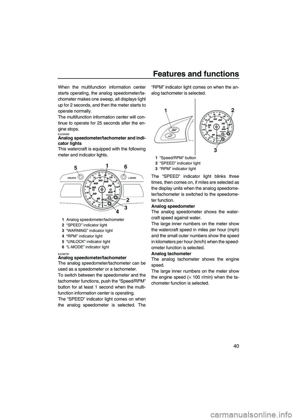
This watercraft is equipped with the following
meter and indicator lights.
EJU36791Analog speedometer/tachometer
The analog speedometer/tachometer can be
used as a speedometer or a tachometer.
To switch between the speedometer and the
tachometer functions, push the “Speed/RPM”
button for at least 1 second when the multi-
function information center is operating.
The “SPEED” indicator light comes on when
the analog speedometer is selected. The“RPM” indicator light comes on when the an-
alog tachometer is selected.
The “SPEED” indicator light blinks three
times, then comes on, if miles are selected as
the display units when the analog speedome-
ter/tachometer is switched to the speedome-
ter function.
Analog speedometer
The analog speedometer shows the water-
craft speed against water.
The large inner numbers on the meter show
the watercraft speed in miles per hour (mph)
and the small outer numbers show the speed
in kilometers per hour (km/h) when the speed-
ometer function is selected.
Analog tachometer
The analog tachometer shows the engine
speed.
The large inner numbers on the meter show
the engine speed (× 100 r/min) when the ta-
chometer function is selected.
1Analog speedometer/tachometer
2“SPEED” indicator light
3“WARNING” indicator light
4“RPM” indicator light
5“UNLOCK” indicator light
6“L-MODE” indicator light
1“Speed/RPM” button
2“SPEED” indicator light
3“RPM” indicator light
UF2H70E0.book Page 40 Thursday, January 15, 2009 10:49 AM
Page 51 of 106
Features and functions
44
Voltmeter
The voltmeter is provided to display the volt-
age of the battery.
When the battery voltage is normal, the volt-
meter displays approximately 12 volts.
If the battery voltage is less than 8.0 volts,
“LO” is displayed on the voltmeter and if the
voltage is above 18.1 volts, “HI” is displayed
on the voltmeter. If “HI” or “LO” is displayed,
return to shore and, if necessary, have a
Yamaha dealer check the charging system
and the battery.
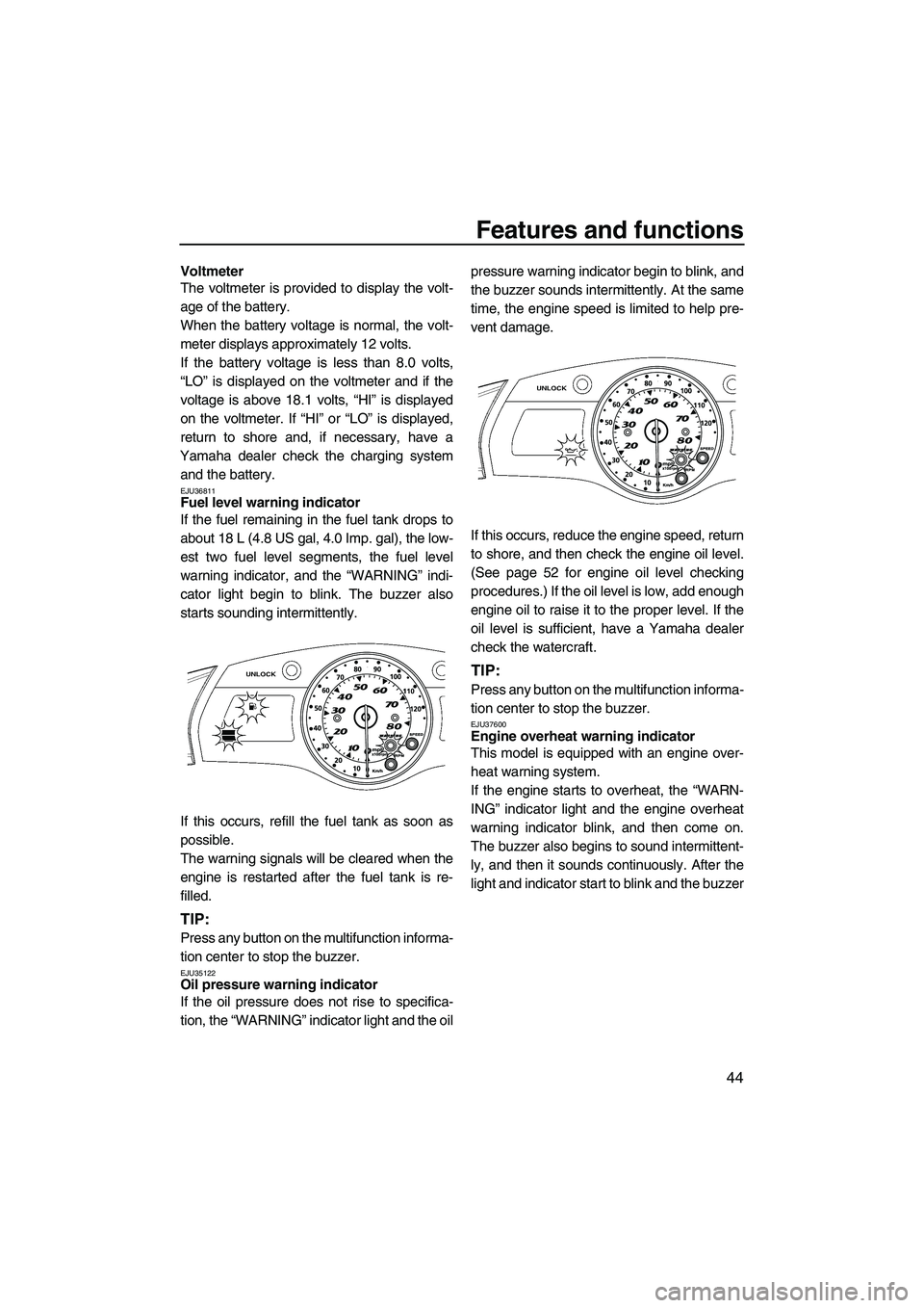
EJU36811Fuel level warning indicator
If the fuel remaining in the fuel tank drops to
about 18 L (4.8 US gal, 4.0 Imp. gal), the low-
est two fuel level segments, the fuel level
warning indicator, and the “WARNING” indi-
cator light begin to blink. The buzzer also
starts sounding intermittently.
If this occurs, refill the fuel tank as soon as
possible.
The warning signals will be cleared when the
engine is restarted after the fuel tank is re-
filled.
TIP:
Press any button on the multifunction informa-
tion center to stop the buzzer.
EJU35122Oil pressure warning indicator
If the oil pressure does not rise to specifica-
tion, the “WARNING” indicator light and the oilpressure warning indicator begin to blink, and
the buzzer sounds intermittently. At the same
time, the engine speed is limited to help pre-
vent damage.
If this occurs, reduce the engine speed, return
to shore, and then check the engine oil level.
(See page 52 for engine oil level checking
procedures.) If the oil level is low, add enough
engine oil to raise it to the proper level. If the
oil level is sufficient, have a Yamaha dealer
check the watercraft.
TIP:
Press any button on the multifunction informa-
tion center to stop the buzzer.
EJU37600Engine overheat warning indicator
This model is equipped with an engine over-
heat warning system.
If the engine starts to overheat, the “WARN-
ING” indicator light and the engine overheat
warning indicator blink, and then come on.
The buzzer also begins to sound intermittent-
ly, and then it sounds continuously. After the
light and indicator start to blink and the buzzer
UF2H70E0.book Page 44 Thursday, January 15, 2009 10:49 AM
Page 68 of 106
![YAMAHA FX HO CRUISER 2009 Owners Manual Operation
61
pebbles or sand could be sucked into
the jet intake, causing impeller dam-
age and engine overheating.
[ECJ00471]
(3) Attach the engine shut-off cord (lanyard)
to your left wrist, and th YAMAHA FX HO CRUISER 2009 Owners Manual Operation
61
pebbles or sand could be sucked into
the jet intake, causing impeller dam-
age and engine overheating.
[ECJ00471]
(3) Attach the engine shut-off cord (lanyard)
to your left wrist, and th](/manual-img/51/49831/w960_49831-67.png)
Operation
61
pebbles or sand could be sucked into
the jet intake, causing impeller dam-
age and engine overheating.
[ECJ00471]
(3) Attach the engine shut-off cord (lanyard)
to your left wrist, and then attach the clip
to the engine shut-off switch. It is not pos-
sible to start the engine with the clip re-
moved from the engine shut-off switch.
WARNING! Check that the engine
shut-off cord (lanyard) is attached cor-
rectly. If the engine shut-off cord (lan-
yard) is not attached correctly, it may
not pull free when the operator falls
off, allowing the watercraft to continue
to run and cause an accident.
[EWJ00581]
(4) Push the start switch (green button), and
then release it as soon as the engine
starts to run. If the engine does not startin 5 seconds, release the start switch,
wait 15 seconds, and then try again. The
engine will not start if the throttle lever is
squeezed. NOTICE: Never push the
start switch while the engine is run-
ning. Do not operate the start switch
for more than 5 seconds, otherwise
the battery will be discharged and the
engine will not start. Also, the starter
motor could be damaged.
[ECJ01040]
EJU32861
Stopping the engine
To stop the engine, release the throttle lever,
and then push the engine stop switch (red
button). WARNING! You need throttle to
steer. Shutting the engine off can cause
you to hit an obstacle you are attempting
to avoid. A collision could result in severe
injury or death.
[EWJ00601]
1Clip
2Engine shut-off switch
3Engine shut-off cord (lanyard)
31
2
UF2H70E0.book Page 61 Thursday, January 15, 2009 10:49 AM
Page 103 of 106
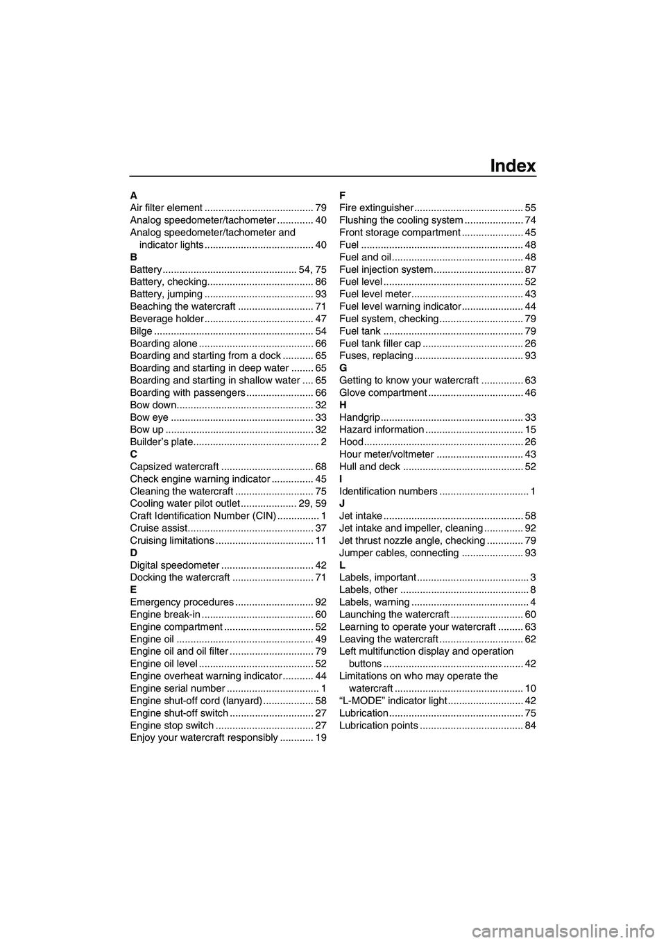
Index
A
Air filter element ....................................... 79
Analog speedometer/tachometer ............. 40
Analog speedometer/tachometer and
indicator lights ....................................... 40
B
Battery ................................................ 54, 75
Battery, checking...................................... 86
Battery, jumping ....................................... 93
Beaching the watercraft ........................... 71
Beverage holder ....................................... 47
Bilge ......................................................... 54
Boarding alone ......................................... 66
Boarding and starting from a dock ........... 65
Boarding and starting in deep water ........ 65
Boarding and starting in shallow water .... 65
Boarding with passengers ........................ 66
Bow down................................................. 32
Bow eye ................................................... 33
Bow up ..................................................... 32
Builder’s plate............................................. 2
C
Capsized watercraft ................................. 68
Check engine warning indicator ............... 45
Cleaning the watercraft ............................ 75
Cooling water pilot outlet .................... 29, 59
Craft Identification Number (CIN) ............... 1
Cruise assist............................................. 37
Cruising limitations ................................... 11
D
Digital speedometer ................................. 42
Docking the watercraft ............................. 71
E
Emergency procedures ............................ 92
Engine break-in ........................................ 60
Engine compartment ................................ 52
Engine oil ................................................. 49
Engine oil and oil filter .............................. 79
Engine oil level ......................................... 52
Engine overheat warning indicator ........... 44
Engine serial number ................................. 1
Engine shut-off cord (lanyard) .................. 58
Engine shut-off switch .............................. 27
Engine stop switch ................................... 27
Enjoy your watercraft responsibly ............ 19F
Fire extinguisher ....................................... 55
Flushing the cooling system ..................... 74
Front storage compartment ...................... 45
Fuel .......................................................... 48
Fuel and oil............................................... 48
Fuel injection system ................................ 87
Fuel level .................................................. 52
Fuel level meter ........................................ 43
Fuel level warning indicator ...................... 44
Fuel system, checking .............................. 79
Fuel tank .................................................. 79
Fuel tank filler cap .................................... 26
Fuses, replacing ....................................... 93
G
Getting to know your watercraft ............... 63
Glove compartment .................................. 46
H
Handgrip ................................................... 33
Hazard information ................................... 15
Hood ......................................................... 26
Hour meter/voltmeter ............................... 43
Hull and deck ........................................... 52
I
Identification numbers ................................ 1
J
Jet intake .................................................. 58
Jet intake and impeller, cleaning .............. 92
Jet thrust nozzle angle, checking ............. 79
Jumper cables, connecting ...................... 93
L
Labels, important ........................................ 3
Labels, other .............................................. 8
Labels, warning .......................................... 4
Launching the watercraft .......................... 60
Learning to operate your watercraft ......... 63
Leaving the watercraft .............................. 62
Left multifunction display and operation
buttons .................................................. 42
Limitations on who may operate the
watercraft .............................................. 10
“L-MODE” indicator light ........................... 42
Lubrication................................................ 75
Lubrication points ..................................... 84
UF2H70E0.book Page 1 Thursday, January 15, 2009 10:49 AM