Page 37 of 108

INSTRUMENT AND CONTROL FUNCTIONS
3-23
3
EAU39492
Seats Passenger seat
To remove the passenger seat1. Insert the key into the passenger
seat lock, and then turn it counter-
clockwise.
2. Lift the front of the passenger seat
and pull it forward.To install the passenger seat
1. Insert the projections on the rear of
the passenger seat into the seat
holders as shown, and then push
the front of the seat down to lock it
in place.
2. Remove the key.
Rider seat
To remove the rider seat1. Remove the passenger seat.
2. Push the rider seat lock lever, lo-
cated under the back of the rider
seat, to the left as shown, and then
pull the seat off.To install the rider seat
1. Insert the projection on the front of
the rider seat into the seat holder
as shown, and then push the rear
of the seat down to lock it in place.
1. Passenger seat lock
2. Unlock.
1. Projection
2. Seat holder
1. Rider seat lock lever
2. Rider seat
1. Projection
2. Seat holder
U2D2E3E0.book Page 23 Friday, September 26, 2008 3:51 PM
Page 38 of 108
INSTRUMENT AND CONTROL FUNCTIONS
3-24
32. Install the passenger seat.
TIP�
Make sure that the seats are prop-
erly secured before riding.
�
The rider seat height can be ad-
justed to change the riding posi-tion. (See page 3-24.)
EAU39632
Adjusting the rider seat height The rider seat height can be adjusted to
one of two positions to suit the rider’s
preference.
The rider seat height was adjusted to
the lower position at delivery.
To change the rider seat height to
the high position
1. Remove the rider seat. (See page
3-23.)
2. Remove the rider seat height posi-
tion adjuster by pulling it upward.3. Move the rider seat holder cover to
the lower position as shown.
4. Install the rider seat height position
adjuster so that the “H” mark is
aligned with the match mark.1. Low position
2. High position
1. Rider seat height position adjuster
1. Rider seat holder cover
U2D2E3E0.book Page 24 Friday, September 26, 2008 3:51 PM
Page 65 of 108
PERIODIC MAINTENANCE AND ADJUSTMENT
6-7
6
EAU18771
Removing and installing pan-
els The panels shown need to be removed
to perform some of the maintenance
jobs described in this chapter. Refer to
this section each time a panel needs to
be removed and installed.
EAU39550
Panel A
To remove the panelRemove the bolts and the quick fasten-
er, and then take the panel off.To install the panel
Place the panel in the original position,
and then install the bolts and the quick
fastener.
EAU47050
Panels B and C
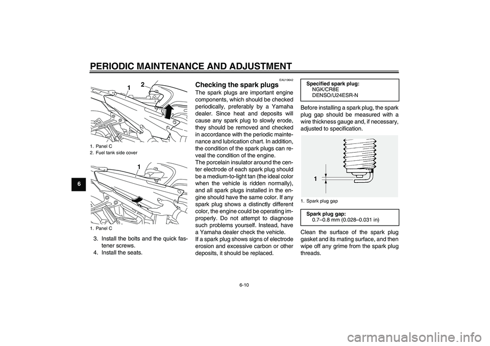
To remove one of the panels1. Remove the seats. (See page
3-23.)
2. Remove the bolts and the quick
fastener screws.
1. Panel A
1. Panel B
1. Panel C
1. Panel A
2. Bolt
3. Quick fastener
U2D2E3E0.book Page 7 Friday, September 26, 2008 3:51 PM
Page 68 of 108

PERIODIC MAINTENANCE AND ADJUSTMENT
6-10
6
3. Install the bolts and the quick fas-
tener screws.
4. Install the seats.
EAU19642
Checking the spark plugs The spark plugs are important engine
components, which should be checked
periodically, preferably by a Yamaha
dealer. Since heat and deposits will
cause any spark plug to slowly erode,
they should be removed and checked
in accordance with the periodic mainte-
nance and lubrication chart. In addition,
the condition of the spark plugs can re-
veal the condition of the engine.
The porcelain insulator around the cen-
ter electrode of each spark plug should
be a medium-to-light tan (the ideal color
when the vehicle is ridden normally),
and all spark plugs installed in the en-
gine should have the same color. If any
spark plug shows a distinctly different
color, the engine could be operating im-
properly. Do not attempt to diagnose
such problems yourself. Instead, have
a Yamaha dealer check the vehicle.
If a spark plug shows signs of electrode
erosion and excessive carbon or other
deposits, it should be replaced.Before installing a spark plug, the spark
plug gap should be measured with a
wire thickness gauge and, if necessary,
adjusted to specification.
Clean the surface of the spark plug
gasket and its mating surface, and then
wipe off any grime from the spark plug
threads.
1. Panel C
2. Fuel tank side cover
1. Panel C
1
21
Specified spark plug:
NGK/CR8E
DENSO/U24ESR-N1. Spark plug gapSpark plug gap:
0.7–0.8 mm (0.028–0.031 in)
U2D2E3E0.book Page 10 Friday, September 26, 2008 3:51 PM