Page 90 of 142
8-15
1
2
3
4
5
6
78
9
10
11
4. Remove the radiator cap. 5. Remove the coolant reservoir cap.
1. Coolant drain bolt
11
1. Radiator cap1
Page 91 of 142
8-16
1
2
3
4
5
6
78
9
10
11
6. Disconnect the hose on the coolant reservoir
side and drain the coolant from the coolant
reservoir.7. After draining the coolant, thoroughly flush the
cooling system with clean tap water.
8. Replace the coolant drain bolt washers if they
are damaged, and then tighten the coolant
drain bolts to the specified torque.
9. Connect the coolant reservoir hose.
10. Pour the recommended coolant into the reser-
1. Coolant reservoir cap
1
1. Coolant reservoir hose
2. Coolant reservoir
Tightening torque:
Coolant drain bolt:
14 Nm (1.4 m·kgf, 10 ft·lbf)
1
2
Page 92 of 142

8-17
1
2
3
4
5
6
78
9
10
11
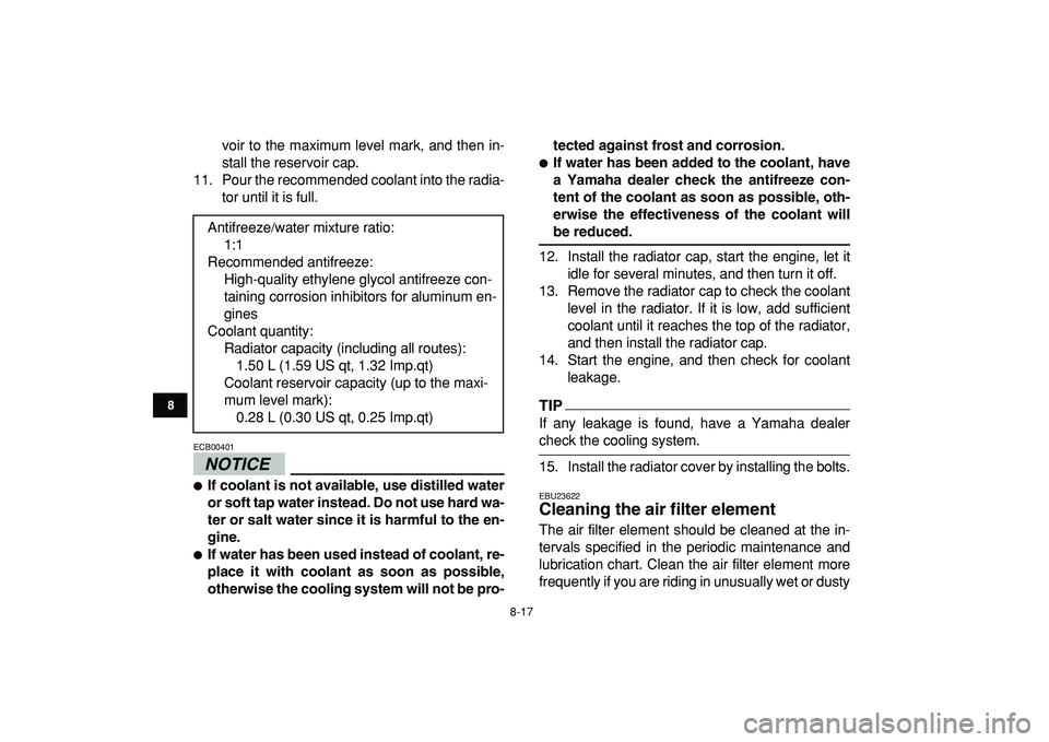
voir to the maximum level mark, and then in-
stall the reservoir cap.
11. Pour the recommended coolant into the radia-
tor until it is full.
NOTICE
ECB00401
�
If coolant is not available, use distilled water
or soft tap water instead. Do not use hard wa-
ter or salt water since it is harmful to the en-
gine.
�
If water has been used instead of coolant, re-
place it with coolant as soon as possible,
otherwise the cooling system will not be pro-tected against frost and corrosion.
�
If water has been added to the coolant, have
a Yamaha dealer check the antifreeze con-
tent of the coolant as soon as possible, oth-
erwise the effectiveness of the coolant will
be reduced.
12. Install the radiator cap, start the engine, let it
idle for several minutes, and then turn it off.
13. Remove the radiator cap to check the coolant
level in the radiator. If it is low, add sufficient
coolant until it reaches the top of the radiator,
and then install the radiator cap.
14. Start the engine, and then check for coolant
leakage.
TIP
If any leakage is found, have a Yamaha dealer
check the cooling system.
15. Install the radiator cover by installing the bolts.
EBU23622
Cleaning the air filter element
The air filter element should be cleaned at the in-
tervals specified in the periodic maintenance and
lubrication chart. Clean the air filter element more
frequently if you are riding in unusually wet or dusty Antifreeze/water mixture ratio:
1:1
Recommended antifreeze:
High-quality ethylene glycol antifreeze con-
taining corrosion inhibitors for aluminum en-
gines
Coolant quantity:
Radiator capacity (including all routes):
1.50 L (1.59 US qt, 1.32 Imp.qt)
Coolant reservoir capacity (up to the maxi-
mum level mark):
0.28 L (0.30 US qt, 0.25 Imp.qt)
Page 128 of 142
8-53
1
2
3
4
5
6
78
9
10
11
Engine overheating
WARNING
EWB02290
Wait for the engine and radiator to cool before removing the radiator cap. You could be burned by
hot fluid and steam blown out under pressure. Always put a thick rag over the cap when opening.
Allow any remaining pressure to escape before completely removing the cap.
TIP
If coolant is not available, tap water can be temporarily used instead, provided that it is changed to the rec-
ommended coolant as soon as possible.
Wait until the
engine has cooled.
Check the coolant level in the
reservoir and radiator.
The coolant level
is OK.The coolant level is low.
Check the cooling system
for leakage.
Have a Yamaha dealer check
and repair the cooling system.Add coolant. (See TIP.)
Start the engine. If the engine overheats again, have a
Yamaha dealer check and repair the cooling system.
There is
leakage.
There is
no leakage.
Page 133 of 142

10-2
1
2
3
4
5
6
7
8
910
11
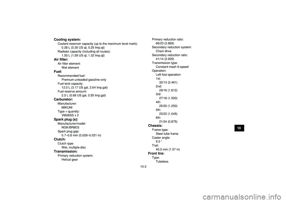
Cooling system:
Coolant reservoir capacity (up to the maximum level mark):
0.28 L (0.30 US qt, 0.25 Imp.qt)
Radiator capacity (including all routes):
1.50 L (1.59 US qt, 1.32 Imp.qt)
Air filter:
Air filter element:
Wet element
Fuel:
Recommended fuel:
Premium unleaded gasoline only
Fuel tank capacity:
12.0 L (3.17 US gal, 2.64 Imp.gal)
Fuel reserve amount:
2.5 L (0.66 US gal, 0.55 Imp.gal)
Carburetor:
Manufacturer:
MIKUNI
Type
×
quantity:
VM26SS x 2
Spark plug (s):
Manufacturer/model:
NGK/BR8ES
Spark plug gap:
0.7–0.8 mm (0.028–0.031 in)
Clutch:
Clutch type:
Wet, multiple-disc
Transmission:
Primary reduction system:
Helical gearPrimary reduction ratio:
66/23 (2.869)
Secondary reduction system:
Chain drive
Secondary reduction ratio:
41/14 (2.929)
Transmission type:
Constant mesh 6-speed
Operation:
Left foot operation
1st:
32/13 (2.461)
2nd:
29/16 (1.812)
3rd:
27/18 (1.500)
4th:
25/20 (1.250)
5th:
23/22 (1.045)
6th:
21/24 (0.875)
Chassis:
Frame type:
Steel tube frame
Caster angle:
9.0 °
Trail:
40.0 mm (1.57 in)
Front tire:
Type:
Tubeless
Page 139 of 142

INDEX
A
Accessories and loading ................................................ 6-6
Air filter element, cleaning ............................................ 8-17
B
Brake and clutch levers, checking and lubricating ....... 8-43
Brake fluid, changing.................................................... 8-35
Brake fluid level, checking............................................ 8-33
Brake lever ..................................................................... 4-5
Brake lever free play, checking the front ...................... 8-35
Brake light switches ..................................................... 8-38
Brake pads, checking the front and rear ...................... 8-32
Brake pedal .................................................................... 4-5
Brake pedal, checking and lubricating ......................... 8-43
Brake pedal position, checking .................................... 8-36
Brakes, front and rear .................................................... 5-3
C
Cables, checking and lubricating ................................. 8-43
Carburetor settings, changing ...................................... 8-22
Chassis fasteners........................................................... 5-7
Cleaning ......................................................................... 9-1
Clutch lever .................................................................... 4-4
Clutch lever free play, adjusting ................................... 8-39
Coolant ................................................................. 5-3
,
8-12
D
Drive chain ..................................................................... 5-4
Drive chain, lubricating ................................................. 8-42Drive chain slack .......................................................... 8-40
E
Engine break-in .............................................................. 6-4
Engine, cold start ........................................................... 6-1
Engine idling speed ...................................................... 8-30
Engine, starting a warm ................................................. 6-2
Engine stop switch ......................................................... 4-2
F
Fuel ................................................................................ 4-8
Fuel and 2-stroke engine oil mixing ratio ....................... 5-3
Fuel cock ........................................................................ 4-9
Fuel tank cap.................................................................. 4-7
H
Handlebar switches ........................................................ 4-2
Headlight beam, adjusting............................................ 8-48
Headlight bulb, replacing.............................................. 8-45
I
Identification numbers .................................................. 11-1
Instruments, lights and switches .................................... 5-7
K
Key identification number ............................................. 11-1
Kickstarter ...................................................................... 4-7
L
Label locations ............................................................... 2-1
Light switch .................................................................... 4-2