2009 VOLKSWAGEN JETTA clock
[x] Cancel search: clockPage 293 of 477
Booklet 3.1 Controls and Equipment
Driving
Steering
Applies lo vehicles: with manually adju stab le steering column
Adjusting the steering wheel position manually
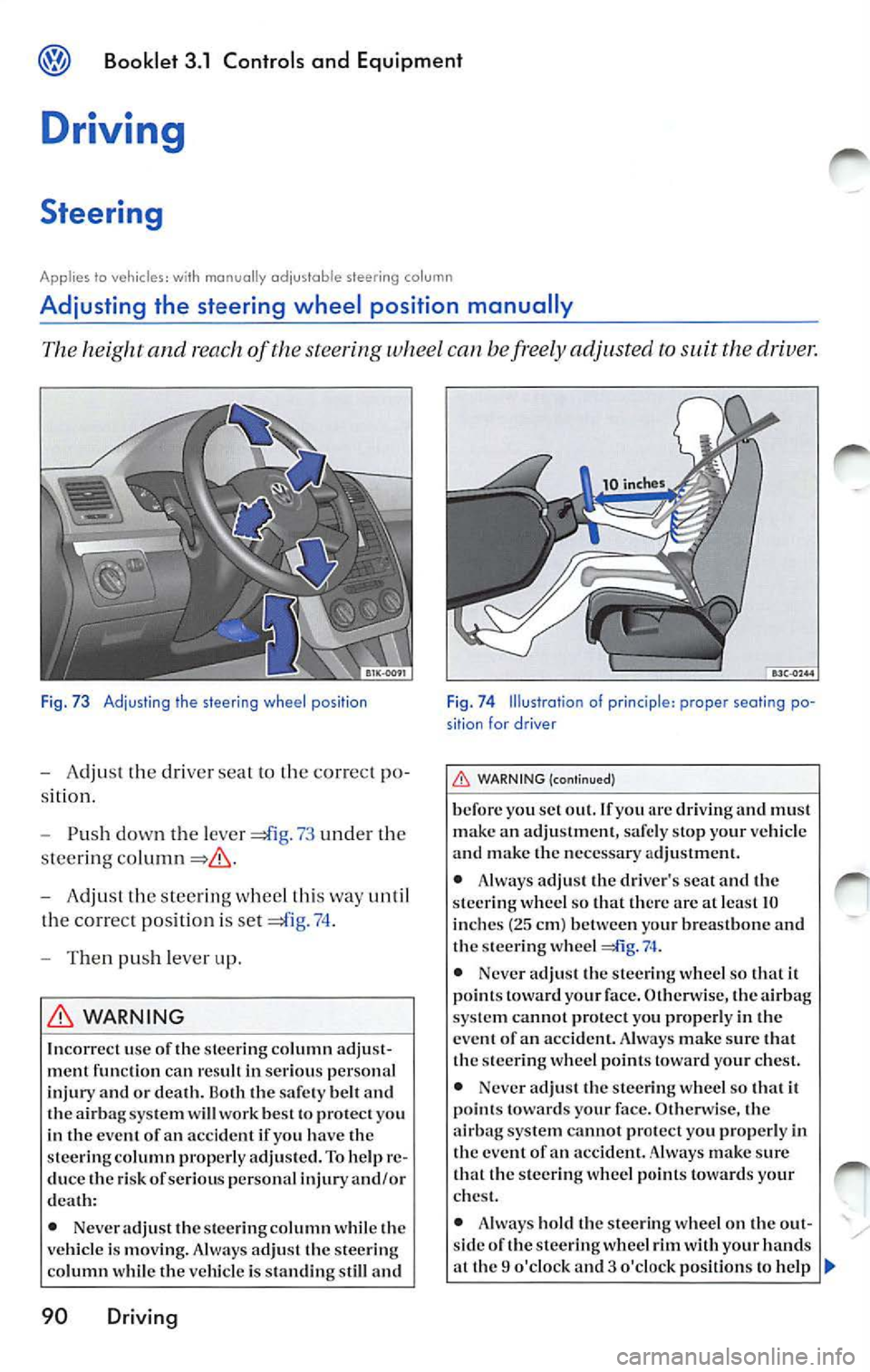
The and reach of the steering whe el can be freely adjusted to suit the driver.
Fi g. 73 Adjusting the stee ring wheel position
- Adj ust the d river sea t to th e cor rect po
s it ion.
- Push dow n the leve r
73 und er th e
s tee rin g
- Adju st th e s teerin g w hee l thi s way until
the corre ct po siti on is se t
74 .
- Then push le ver up .
WARNING
Incorrect use of the steer ing co lumn adjust
ment function can in seriou s per sonal
in ju ry and or death. the sa fety bell and sys tem w ill work best to protec t yo u
in the event of an accident if yo u have the
s teering column properly adjusted. To help re
duce
ri sk of seriou s perso nal injury and /or
death:
• Neve r adjust
steering column whil e vehicle i s moving. Always ad just steering
co lumn whil e the vehicle is standing still and
90 Driving
Fig. 74 Illustratio n of prin ciple: proper seating po
sition for d river
WARN ING (continu ed)
b efore you se t out . If yo u are driving and must
ma ke an adju stment, safely slop your vehicl e
and make
necessary adjustment.
• Always adjust the dri ver 's s cat and the
s teer ing wheel so that there are at leas t 10
in che s (2 5 cm) between your brea stb one and
ste ering whee l
• Neve r adjust the stee ring wheel so Iha! ii points toward your face. Otherw ise, the a irb ag
syste m cann ot prote ct yo u proper ly in
eve nt of an accident. A lway s make sure that steer ing wh eel point s toward your chest .
• Neve r ad just the stee ring whee l so
points towards your face. O then vise, airbag system canno t p ro tect you properl y in eve nt of an accid ent . Always make sure
that the steerin g whe el po int s toward s your
c h es t.
• Alw ays hold
stee ring w heel on out
s id e of steering wheel rim with your hands
a t th e 9 o 'clock 3 o'clock posit ions to help
Page 351 of 477
Booklet 3 .2 Tips and Advice
Checking and Filling
Filling the tank
fuel filler flap opens from inside the vehicle. The fuel tank holds 14 .5 gallons
(55 Liters).
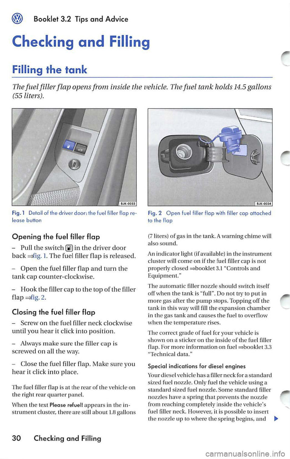
Fig . 1 Detail of the driver door: the fuel fil ler flop re
lease button
Opening the fuel filler flap
- Pull the switc h 00) in th e drive r doo r
back
I. T he fu el fill er flap i s re leased .
- Open the fuel filler flap and turn th e
tank cap counte r-cloc kw ise.
- Hook t he fill er cap to the top of the filler
flap
2 .
Clo sing the fuel filler flap
- Screw o n the fuel fi lle r ne ck clockwise
until you hea r it cl ick into position.
- Alway s m ake s ure the fi ller cap i s
screwe d on a ll way.
- Close the fuel fi ller flap. Make sure you
h ear it cli ck into place.
The fue l filler flap is at the re ar of the vehicle on
th e right re ar qua rter pan el.
Whe n the tex t Pleas e refuel! appears in the in
s trum ent clu ste r, th ere a re still abo ut
gallons
30 Checking and Filling
Fig. 2 Open fuel filler flap with f iller cap attached
to the flop
(7 liter s) of gas in the tank. A warning chi me w ill
a lso so und.
An indi cator lig ht (if availab le) in the in st rum ent
cluster w ill come on if the fu el fi ller cap is not
properly clos ed
3.1 "C ontrol s and
Eq uipment."
T he automat ic filler nozzle s hould switc h itself
when the tank is " full ". Do not try to put in
mor e gas after the pump stops. To ppin g off the
ta nk in this
will fill the expa nsion chamb er
i n th e gas tank and causes th e fuel to ove rflow
w hen the temperature ri ses.
The correct grade of fuel for your vehicle is
s h own o n
sti cker on the insid e of the fuel filler
flap. For mor e informatio n on fu el 3.3
" T ec hnical da ta ."
Specia l indications far diesel engines
Your diesel vehi cle ha s a filler neck for a sta ndard
s ized fuel noz zle. Onl y fuel the v ehicl e usin g a
s tan dard sized fuel nozz le. Some s tandard filler
no zzles have a sprin g that preve nts the nozzle
from reaching complete ly ins ide t he ve hicl e's
fille r neck. However, it is poss ible to t h e nozzl e up to wh ere the spring beg ins, an d
Page 367 of 477

Booklet 3.2 Tips and Ad vic e
Changing windshield wiper blades
Dama ged wiper blades must be rep lac ed
Fig . 10 Windsh iel wiper blades in "Service posi tion"
Regularl y check the co nditi on of the wipe r
blad es. Change them when worn.
Chang ing windshield wip er blades
- Switch the ignition on briefl y and
sw itch it back off.
- Wit hin IO seconds of switching
th e
i g ni tion, push the windshi eld wiper lever
down to the brie f w ipin g position. The
w indshield wip ers w ill then mo ve up and
stop in the "Service posit ion " so that you
can easily access the wipe r blade s
IO .
- Lift th e wiper arm away from the w ind
s hield glass. Do not pull th e arm by th e
bl ad e.
- Turn the wiper blade in a counter
cl oc kwise directio n to the lef t
I I
and then pull it
- In sta ll a n ew wipe r blade of the same
l eng th and type onto the w ip er arm and
t urn th e w ip er bl ade clockwi se.
46 Checking and Filling
Fig. 11 Changing windshie ld wiper blades
- Put the wip er arms back agains t the
w indshie ld. The win dsh ie ld wiper arms
wi ll re turn to their original po sition w hen
you turn on the ignit ion and opera te th e
w ind shi eld wipe r lever or w hen yo u dri ve
faster than 3 mph (6km /h ).
Replac ement wip er blad es are available from
y our au thorized Volkswage n deal er.
I f th e w ind shi eld wiper s rub , or if they are dam
ag ed
shou ld be rep laced , or clea ned if th ey
are dirty.
If th is do es
produ ce de sired re sult s, settin g angle of winds hield wiper arm s ma y
be in correct sh ould be ch eck ed an d ad if necessary by an dealer or quali fied work sh op .
WARNING
Worn or wip er b la d es w ill redu ce vis i
bilit y and increase the risk of acci dent l ead ing
to ser io us perso nal inju ry to you and your p as
se nger s.
•
clea n wind shi eld wip er blade s
and all wi ndo ws reg ular ly.
• Alw ays mak e sure to ch an ge the
blade s onc e or tw ice a yea r.
Page 378 of 477
"Tires and ve hicl e lo ad limit s" for more imporinfor mati on.
Vehicles
ha ve full hub caps have valve ex
tenders ins tead of du st caps. To ch eck tire pr es
s ur e or acid air. you do not n eed to re move the
ex te nd er. 13e s ure to rein sta ll va lve dust caps
ch eck ing or adjust ing tir e pr ess ure.
A lways use an
tir e pr ess ure gaug e w hen
c h eck ing and adju stin g i nfl atio n pr essu res .
C hec k all of the
and b e sure not l o forg et th e
s par e tire. If p ress ure in an y is too high
w hen the tire is "co ld," let o ur of the tir e
s lowly with th e of the tir e ga uge and kee p
c h eck ing th e press ure until you re ac h th e pr es
s ure that is correc t for th e loa d (pa sse nge rs and
l u gg age)
ki nd of dri ving yo u plan t o do .
I f th e pr ess ure in any tire is too low , n ote the dif
f e re n ce between the press ure in the co ld
a nd
th e pr ess ure yo u need and add air yo u
n eed to reac h th e co rrect press ure for the vehicle
load (pa sse nge rs and lu ggage) for th e tire s on
yo ur vehicle as listed o n the on yo ur vehicle a nd
in thi s man ual
th e kind of driv ing y ou p lan
t o do .
Neve r excee d th e maxi mum infl ati on pre ssure
li sted on the tir e sid ewa ll for any reason.
R em emb er th at the ve hicle manufac turer, not
t h e tir e man ufa ctur er, de te rmin es th e co rrec t
t ir e pr ess ure for th e tir es o n yo ur vehicle
I t i s imp ortant
ch ec k th e tir e pr ess ure when
the tires are cold.
Vehicle witho ut
• the re quir ed tire pressure from the tir e
pressu re lab el on the ope n edge of th e dri ver's
door .
• Place the a ir press ure gauge on the dust cap s
- th ere is no need
re m ove them.
• The tir e press ures s ho uld onl y be checked
tire s cold. The sli ghtl y pres
s ur es ofwann tires no t b e reduced.
•
th e tire press ure to the load you are
ca rrying.
Vehicle with
• the req uir ed tir e pr ess ure from the tir e
pressure label o n th e ope n edge of the dr ive r's
do or.
Booklet 3.2 Tips and Advice
• Turn th e va lve s tem cap counter-clockw ise to
r emove it from the tire valve.
•
th e ai r press ure on the valv e.
• The tir e pressures sh o uld onl y be ch ecke d
w hen th e tir es are cold. T he slig htly rai sed pres
s ur es of
tires not be redu ced.
• Adju st th e tir e pr ess ure to the load you are
carry ing.
• Reins tall the valv e ste m cap on the valve.
When should I ch eck the tire pressure?
Th e co rrec t tir e pr ess ure is especia lly import ant
a t hi gh speeds . Th e pre ssur e s ho uld th erefo re be
c h ecked at leas t once a month and alwa ys befo re
s ta rt in g a jo urn ey. D o not forget to ch eck the tire
pr ess ure on th e spare whee l
When shou ld
I adjust the tire press ures?
Ad just th e tire press ure to the loa d you are car
ry ing. After changin g
wheel or repl acing
w hee ls yo u have tu adj ust th e tir e press ures on
a ll whee ls. In ad ditio n on ve hicles wit h TPMS,
yo u sh oul d s pecify new tire pressures
=boo klet
WARNING
In co rrec t tire press ure ca n result in sudd en
ti re failur e Jo ss of co ntrol, collision , seriou s
perso nal injur y an d eve n dea th .
•
tire s to the re co mm end ed and
co rrec t tir e pre ssure before drivin g off.
• Driving with und erinfl atcd tires bend
m or e, le ttin g th em get too hot res ulting in
tr ead separatio n, s udd en tir e fai lure ti re
fa ilur e and Jo ss of control.
• Excess ive sp ee d and /or ove rload ing ca n
ca use hea t build -u p, su dden tire failure in
cludin g a bl owo ut an d su dden deflati on and
Jo ss o f co ntrol.
• If th e tire pr essure is to o low or too high,
th e tir es will wear prema turely and the ve hicl e
wi ll not handl e we ll.
Not e
Dr iv in g w ith out valve s te m caps ca n cau se
applicab le Tire pressure monitoring system)
Checking and Filling 57
Page 391 of 477
Booklet 3.2 Tips and Advice
Applies lo vehicles: wi th spore whee l
Removing the spare wheel
The spar e wheel is located und ern eath the floor covering in the luggag e compart
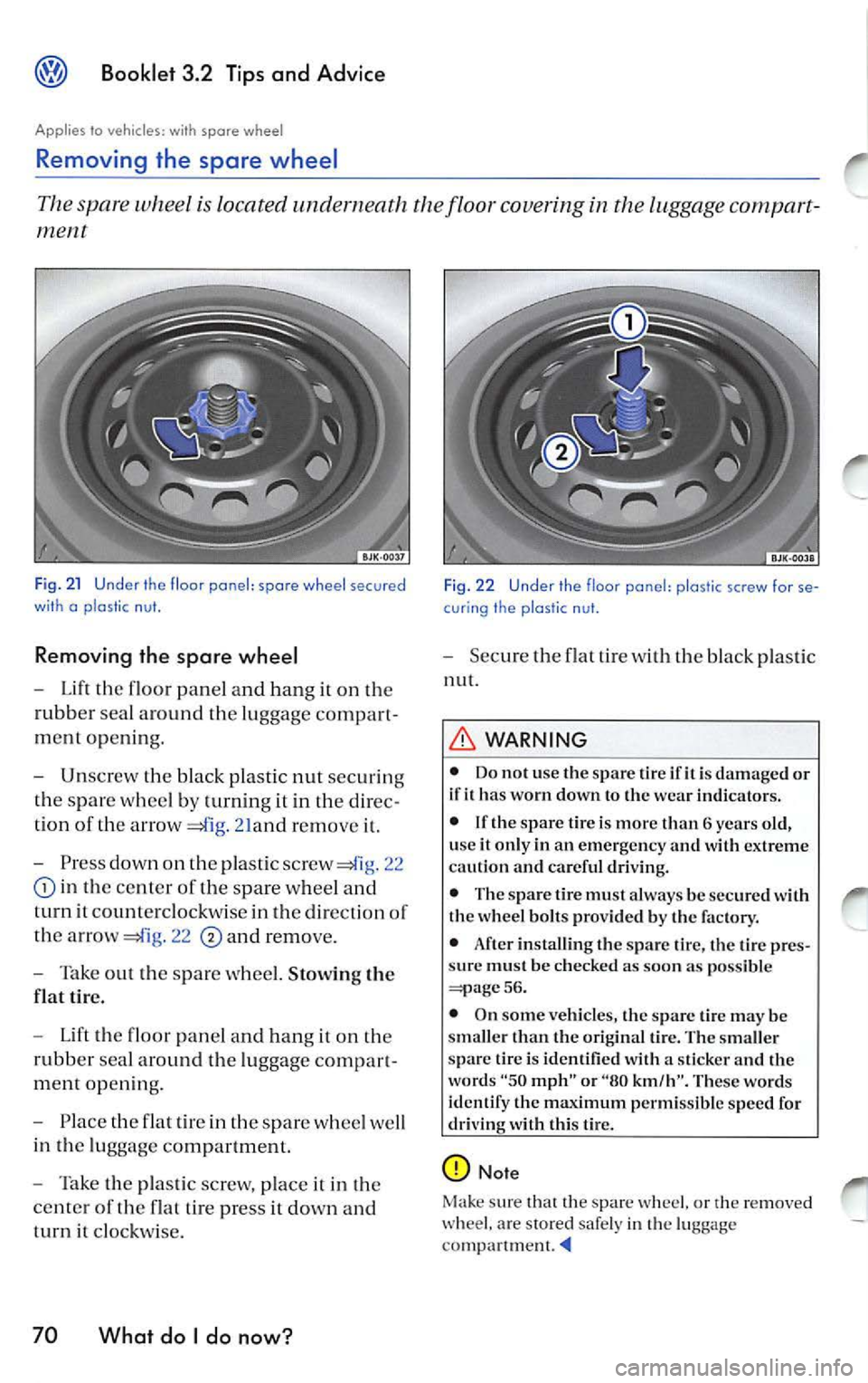
Fig. 21 Under th e floor ponel: spore wheel secured
wi th o p las tic nut.
Removing the spare wheel
-Lift floor panel and hang on
rubb er sea l aro und the luggage compart
ment openin g.
- Unscrew the black plastic nut securin g
th e s par e whee l by turning it in
direc
tion of th e arrow
21and remo ve
-Press dow n on pla stic screw 22
in the ce nter of the spare wheel and
turn it co unt erclo ckw ise in th e direction of
the arro w
22 and remove.
- Tak e out the s pare whee l. Stowing the
flat tir e.
- Lift the fl oor pan el a nd h ang i t on the
rubb er sea l around the luggage compart
m en t open ing.
- Pla ce the flat tir e in the spar e whee l we ll
in the lu ggage co mpartment.
- Take the pla stic scr ew, place it in the
c ente r of th e flat tire pre ss
dow n and
t urn
clockw ise.
70 What do I do now?
Fi g. 2 2 Under th e floor pone!: plo stic screw for se
cur ing the plostic n ut.
- Secu re the flat tire w ith bla ck pl astic
nut.
WARNING
• Do not use the spar e tir e ifit i s damaged or
if it ha s worn down to the wear indicators.
• If th e s pare lire i s more than 6 years old,
u se
it only in an em ergen cy and with extreme
cau tion and careful dri vin g.
• The spare tire mu st alwa ys be se cur ed w ith
the wheel bolt s provided b y the factory.
• After installin g the spare tire, the tire pr es
s ur e must be c hecked as soon as p ossible
56.
• On some ve hicles, the spare tire ma y be
sma ller th an th e original tire. The smaller
spar e tir e is identified with a sticker and th e
word s
"50 mph" or "80 km/h". These words
identify the max imum permissible sp ee d for
driving with this tire.
Not e
Mak e sure that the spare w heel. or
re mo ved ar e stored safe ly i n luggag e
Page 392 of 477
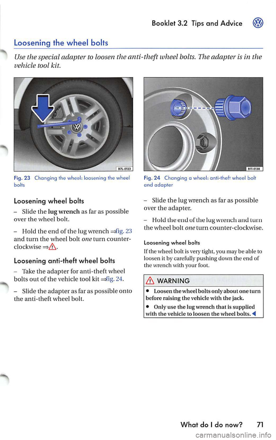
Booklet 3.2 Tips and Advice
Slid e th e lu g wrench as far as possib le
over the whee l bolt.
Hold the end of the lug wre n ch 23
and turn the whee l bolt
one turn count er
Loosening anti-theft wheel bolts
Take the adapter for ant i- th eft w hee l
bol ts out of the ve hicle tool kit =£lg. 24 .
Slid e the adap ter as far as pos sib le o nto
th e a nti -theft w hee l b olt.
Fig . 2 4 Chang ing a wheel : ant i- t h eft whe el b olt
and adopte r
Slid e the lug w rench as far as possib le
ove r the adapter.
uf turn
th e whee l bolt one turn counter-clockwi se.
Loosen ing wheel bolts
If th e w hee l b olt is very tigh t, yo u may be able t o loose n it by carefu lly pu shin g down the end of
th e wre nch with your foo t.
WARNING
• Loo sen th e whee l bolt s onl y about one turn
b efor e rai sing th e vehicle w ith the jack.
• Only use the lu g wrench that is suppli ed
w ith th e ve hicl e to loosen the wheel
What do I do now? 71
Page 394 of 477
WARNING {continu ed)
• Never let anyone place any part of their
body underneath the vehicle when support ed
by the jack.
• Never support your vehicl e on cinder
blocks, bricks or other obje cts . These may not
Changing a wheel
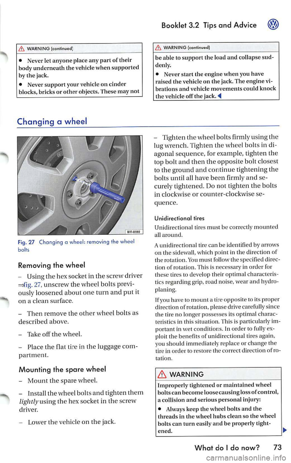
F ig . 27 Chang ing a wheel : removing the wheel
baits
Removing the wheel
-Usin g the h ex socket in th e sc rew dri ver
27, un screw t he w heel bo lts pre vi
o usly loo sen ed about on e turn and put it
o n a cl ean su rface .
- Then re mo ve the oth er whee l bolt s as
d esc ribed abo ve.
- Tak e off th e w he el.
- Place the flat ti re in the lu gg ag e co m-
p artmen t.
Mounting the spare wheel
-Mount the sp a re wh eel.
- Insta ll th e w hee l bolt s and tight en th em
lig htly u sin g th e hex so cke t in th e sc rew
dri ver.
- L ower th e ve hicle on the jack .
Booklet 3.2 Tips and Advice
WARNING {cont inu ed )
be able to support the load and collap se sud
denl y.
• Nev er start the engine when you have
raised the vehicl e on the jack. The engine vi
bration s and v ehicle movements could knock
the v ehicl e off the
- T ig ht en the wheel bolts firml y using the
lu g w re n ch. Ti gh te n th e whee l b olts in di
a gonal s equ ence , for e xampl e, tig h te n th e
top bolt and then th e oppo sit e bolt clo se st
to th e ground and continu e tight enin g the
bolt s until all have bee n firml y and se
c ur ely tight en ed. Do not tight en th e bolts
in clock wise or c ounter-cl oc kw ise se
quen ce.
Unidirectional tires
Unidir ectional tir es mu st be co rrec tly m ount ed
a ll arou nd.
A un idir ection al tir e ca n b e id en tified b y arrows
o n th e s idewa ll, w hi ch p oin t in the di rec tion of
t h e ro tation . Yo u mu st fo llow the speci fied dir ec
ti on of ro ta ti on. Thi s is necessary in orde r for
the se tires to deve lop t heir optim al cha racte ris
ti cs regar ding grip, road noise, wea r and hydro
p la ni ng .
I f y ou have
to moun t a tire opp osite to i ts pro per
dir ection of rot atio n. p lease drive caref ull y sin ce
th e tir e no lo nge r poss esses its o ptimal chara c
t e ri stic s in thi s s itu atio n. Thi s is parti cul arl y im
po rta nt in we t con ditions. In orde r to f ully ex
pl oi t th e benefi ts of unidir ectio nal tire s ag ain ,
yo u sh ou ld imm edi ate ly re place or change the
tir e in or der to resto re th e co rrect d irec tion of ro
t a ti on .
WARNING
Improp erl y tight en ed or maintain ed wheel
b olt s can b ecome loose cau sin g lo ss of control ,
a colli sio n and seriou s per son al inju ry:
• Alw ay s keep th e wheel bolt s and th e
thread s in the wh eel hub s clean so the whee l
bolt s can turn easily and be p roperl y tight-
en ed .
What do I do now? 73
Page 408 of 477
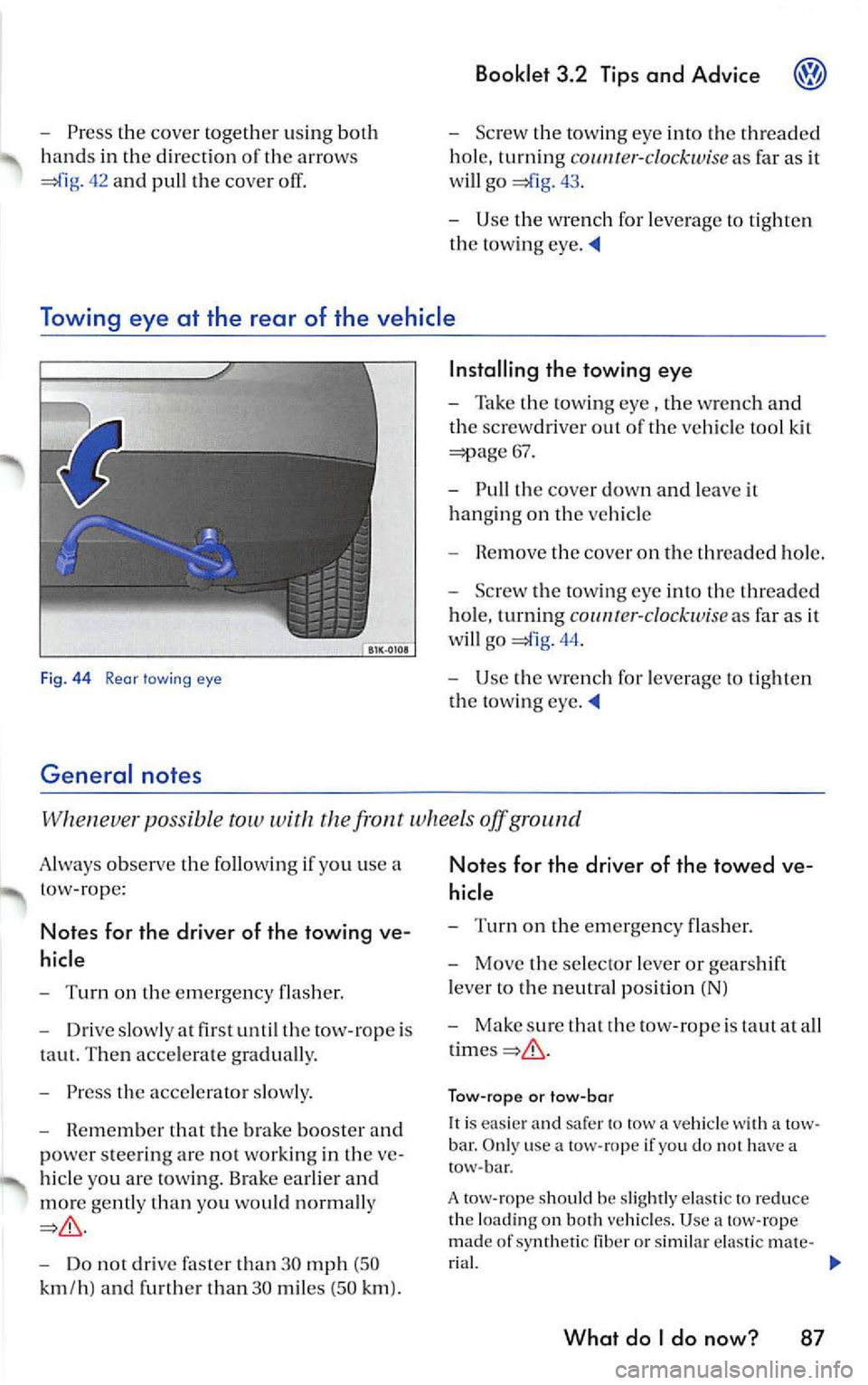
-Press the cove r together u sing both
hand s in the direc tion or th e arrows
42 and pull the cover
Booklet 3.2 Tips and Advice
-Screw th e tow ing eye into the t hread ed
ho le , turnin g
co1111t er-cl ockwi se as far as it
will go
43.
- Use the wre n ch for leverage to tighten
the towing eye.
Towing eye at the rear of the vehicle
Fig. 44 Rear lawing eye
General notes
Installing the towing eye
-Take the towing eye , the wrench a nd
th e sc rew driver out of the vehicl e tool kit
=;:iage 67.
- Pull the cover down and lea ve it
hanging on the vehicl e
- R em ove the cove r on the threaded hole.
- Screw t he towin g eye into th e thr ea ded
hol e, turning
co 1111r er-clockw ise as fa r as it
w ill go
44.
- Use the wrench for leve rage to tight en
the tow ing eye.
po ssi ble tow with the fron t wheels off ground
A lways observe the following use a
t ow-rope :
Notes for the driver of the towing ve
hicle
- Turn on the emerge ncy flas her.
- Driv e slowly at fir st until th e tow-ro pe is
taut. Then acce lerate graduall y.
- Press the acce le rator slow ly .
- Remembe r that the brak e boo ster and
po we r stee rin g ar e not working in the ve
hi cle you are tow ing. Brake earlier and
mor e gently than you wo uld n orm ally
Do not drive than 30 mph (50
k m /h ) and furth er tha n 30 miles (5 0 km ).
Notes for the driver of the towed ve
hicl e
-Turn on the emergency flash er.
- Move the selecto r leve r or gears hi ft
l ever to the neutral posi tion (NJ
- Make sure tha t rh e tow -rope is taut at a ll
Tow-ro pe or tow -bar
It is easier and sa fer to tow a vehicle with a tow
bar . O nl y use a tow- rope if yo u d o no t h ave a
tow -bar.
A tow -rope s hould be sli ghtl y e las tic to re duce
th e lo adin g on both vehicl es. U se
tow-rope
mad e of sy nthetic fib er or sim ilar ela sti c m ate -
r ia l.
What do I do now? 87