2009 SUBARU TRIBECA Room light
[x] Cancel search: Room lightPage 541 of 2453
LI-8
Interior Light System
LIGHTING SYSTEM
7. Interior Light System
A: WIRING DIAGRAM
1. ROOM LIGHT
B: INSPECTION
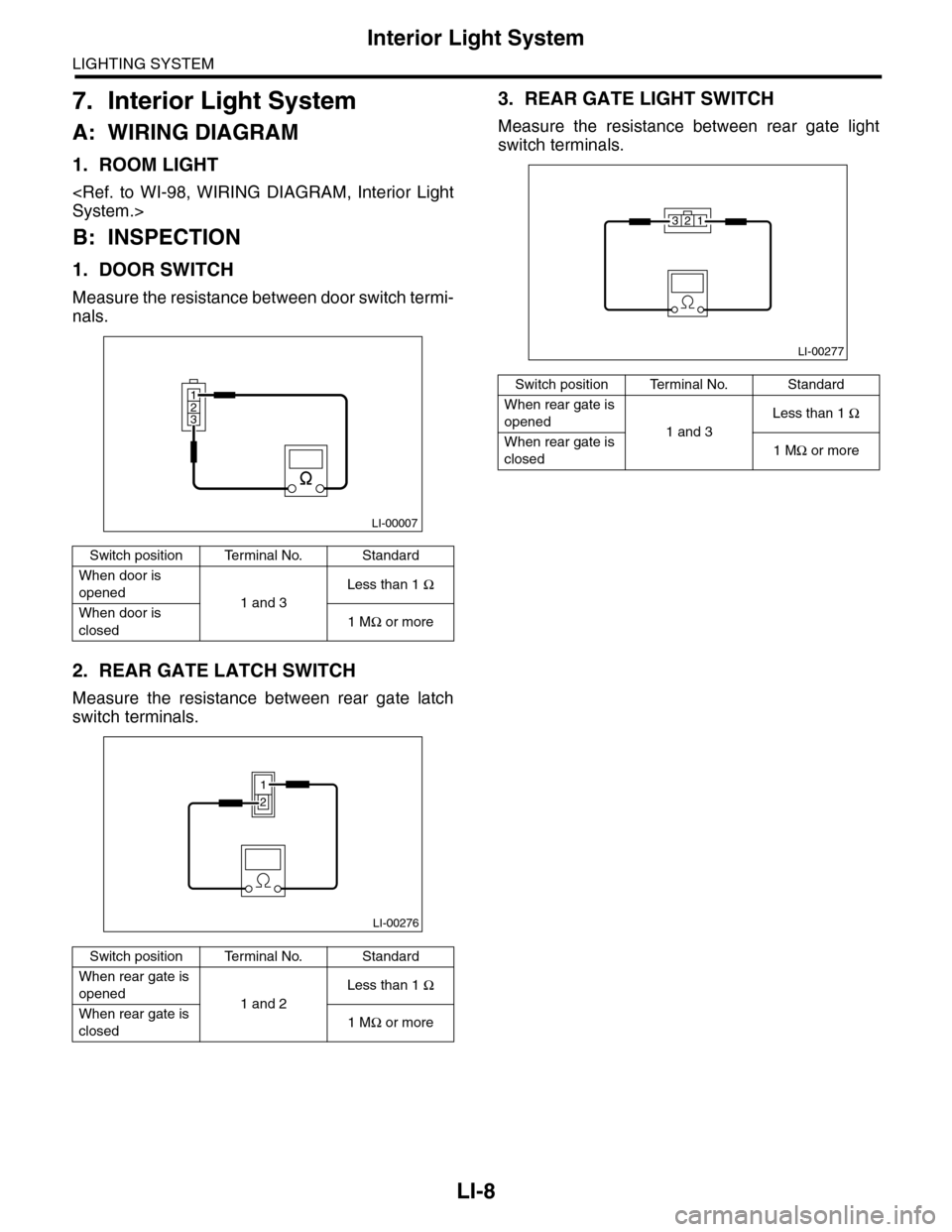
1. DOOR SWITCH
Measure the resistance between door switch termi-
nals.
2. REAR GATE LATCH SWITCH
Measure the resistance between rear gate latch
switch terminals.
3. REAR GATE LIGHT SWITCH
Measure the resistance between rear gate light
switch terminals.
Switch position Terminal No. Standard
When door is
opened1 and 3
Less than 1 Ω
When door is
closed1 MΩ or more
Switch position Terminal No. Standard
When rear gate is
opened1 and 2
Less than 1 Ω
When rear gate is
closed1 MΩ or more
123
LI-00007
LI-00276
1
2
Switch position Terminal No. Standard
When rear gate is
opened1 and 3
Less than 1 Ω
When rear gate is
closed1 MΩ or more
LI-00277
123
Page 563 of 2453
LI-30
Room Light
LIGHTING SYSTEM
28.Room Light
A: REMOVAL
1. MODEL WITHOUT REAR ENTERTAIN-
MENT SYSTEM
1) Disconnect the ground cable from battery.
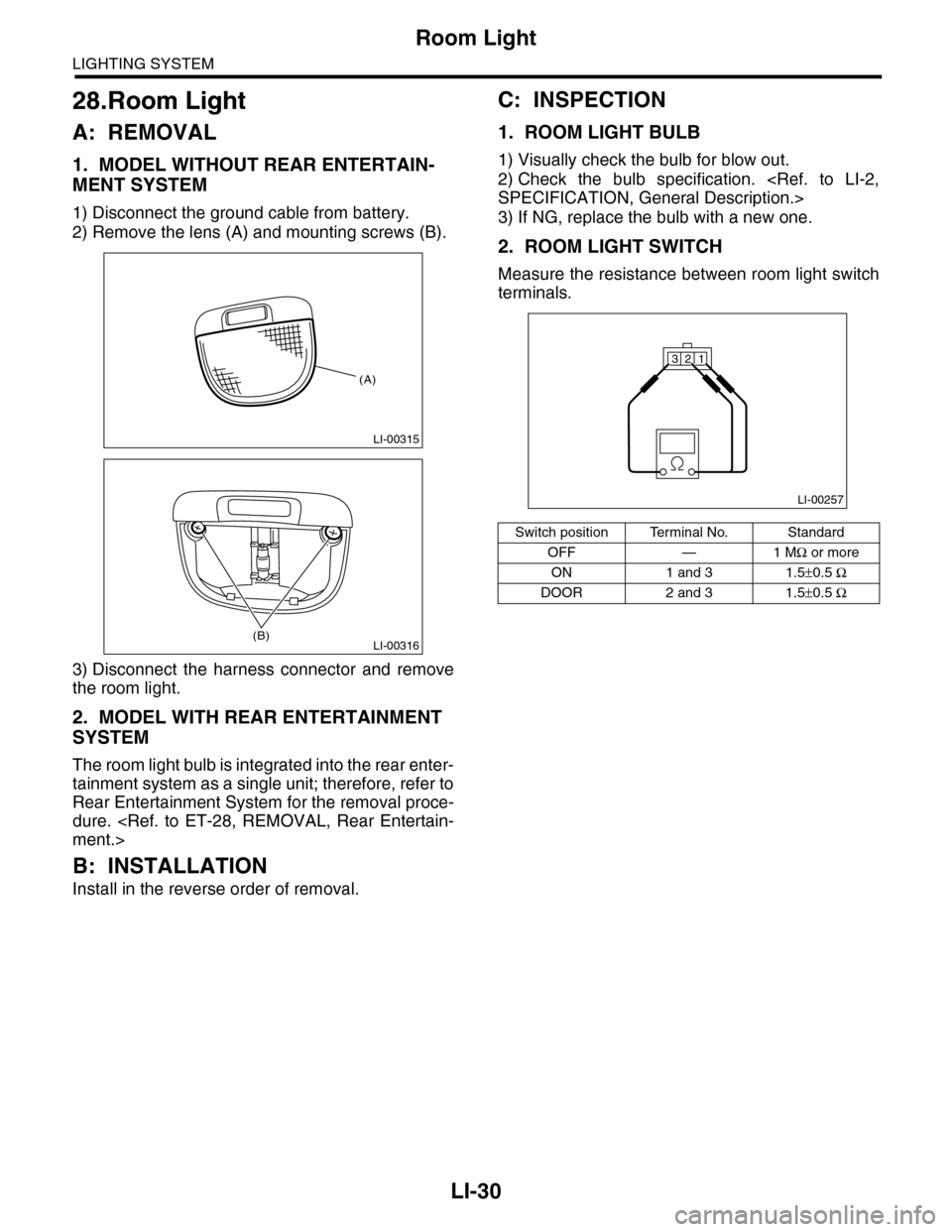
2) Remove the lens (A) and mounting screws (B).
3) Disconnect the harness connector and remove
the room light.
2. MODEL WITH REAR ENTERTAINMENT
SYSTEM
The room light bulb is integrated into the rear enter-
tainment system as a single unit; therefore, refer to
Rear Entertainment System for the removal proce-
dure.
B: INSTALLATION
Install in the reverse order of removal.
C: INSPECTION
1. ROOM LIGHT BULB
1) Visually check the bulb for blow out.
2) Check the bulb specification.
3) If NG, replace the bulb with a new one.
2. ROOM LIGHT SWITCH
Measure the resistance between room light switch
terminals.
LI-00315
(A)
LI-00316(B)
Switch position Terminal No. Standard
OFF — 1 MΩ or more
ON 1 and 3 1.5±0.5 Ω
DOOR 2 and 3 1.5±0.5 Ω
LI-00257
321
Page 564 of 2453
LI-31
Luggage Room Light
LIGHTING SYSTEM
29.Luggage Room Light
A: REMOVAL
1) Disconnect the ground cable from battery.
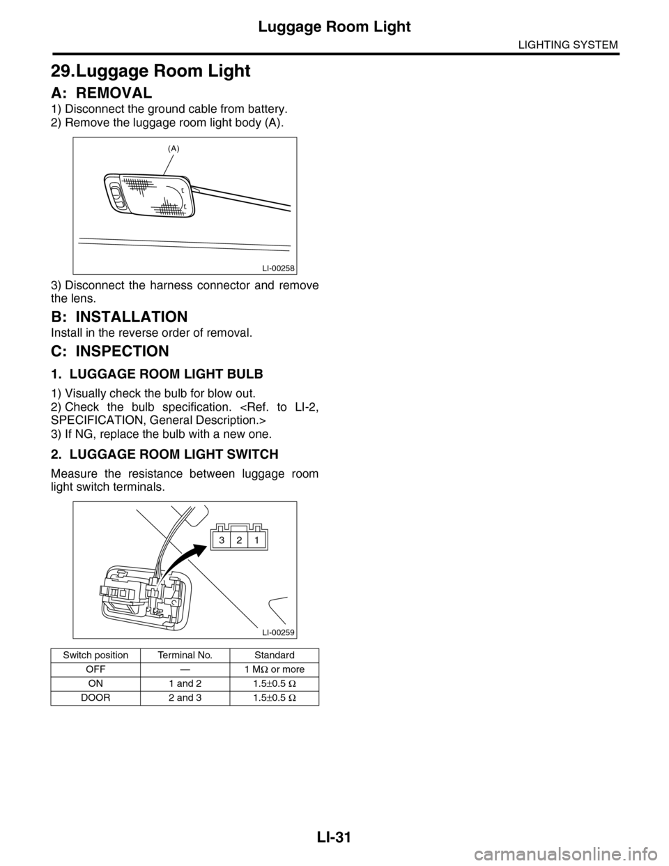
2) Remove the luggage room light body (A).
3) Disconnect the harness connector and remove
the lens.
B: INSTALLATION
Install in the reverse order of removal.
C: INSPECTION
1. LUGGAGE ROOM LIGHT BULB
1) Visually check the bulb for blow out.
2) Check the bulb specification.
3) If NG, replace the bulb with a new one.
2. LUGGAGE ROOM LIGHT SWITCH
Measure the resistance between luggage room
light switch terminals.
Switch position Terminal No. Standard
OFF — 1 MΩ or more
ON 1 and 2 1.5±0.5 Ω
DOOR 2 and 3 1.5±0.5 Ω
LI-00258
(A)
LI-00259
321
Page 641 of 2453
SL-12
Keyless Entry System
SECURITY AND LOCKS
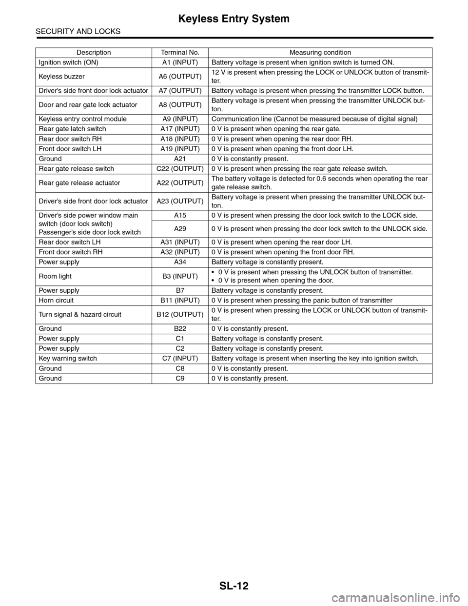
Description Terminal No. Measuring condition
Ignition switch (ON) A1 (INPUT) Battery voltage is present when ignition switch is turned ON.
Keyless buzzer A6 (OUTPU T)12 V is present when pressing the LOCK or UNLOCK button of transmit-
ter.
Driver’s side front door lock actuator A7 (OUTPUT) Battery voltage is present when pressing the transmitter LOCK button.
Door and rear gate lock actuator A8 (OUTPUT)Battery voltage is present when pressing the transmitter UNLOCK but-
ton.
Keyless entr y control module A9 (INPUT) Communication line (Cannot be measured because of digital signal)
Rear gate latch switch A17 (INPUT) 0 V is present when opening the rear gate.
Rear door switch RH A18 (INPUT) 0 V is present when opening the rear door RH.
Fr o nt d oo r swi tc h L H A 19 ( I NP UT ) 0 V i s pr e se n t wh e n o p en in g th e f r o n t d oo r L H.
Ground A21 0 V is constantly present.
Rear gate release switch C22 (OUTPUT) 0 V is present when pressing the rear gate release switch.
Rear gate release actuator A22 (OUTPUT)The battery voltage is detected for 0.6 seconds when operating the rear
gate release switch.
Driver’s side front door lock actuator A23 (OUTPUT)Battery voltage is present when pressing the transmitter UNLOCK but-
ton.
Driver’s side power window main
switch (door lock switch)
Passenger’s side door lock sw itch
A15 0 V is present when pressing the door lock switch to the LOCK side.
A29 0 V is present when pressing the door lock switch to the UNLOCK side.
Rear door switch LH A31 (INPUT) 0 V is present when opening the rear door LH.
Fr o nt d oo r swi tc h RH A 32 ( I NP UT ) 0 V i s pr e se n t wh e n o p en in g th e f r o n t d oo r RH.
Pow er s up p ly A 34 B at t e r y vol t ag e i s c on s ta n tl y p r e se nt .
Room light B3 (INPUT)•0 V is present when pressing the UNLOCK button of transmitter.
•0 V is present when opening the door.
Pow er s up p ly B 7 B at t e r y vol t ag e i s c on s ta n tl y p r e se nt .
Horn circuit B11 (INPUT) 0 V is present when pressing the panic button of transmitter
Tu r n s i g n a l & h a z a r d c i r c u i t B 1 2 ( O U T P U T )0 V is present when pressing the LOCK or UNLOCK button of transmit-
ter.
Ground B22 0 V is constantly present.
Pow er s up p ly C 1 B at t e r y vol t ag e i s c on s ta n tl y p r e se nt .
Pow er s up p ly C 2 B at t e r y vol t ag e i s c on s ta n tl y p r e se nt .
Key war ning switch C7 (INPUT) Batter y voltage is present when inser ting the key into ignition switch.
Ground C8 0 V is constantly present.
Ground C9 0 V is constantly present.
Page 643 of 2453

SL-14
Keyless Entry System
SECURITY AND LOCKS
The panic alarm does not operate. 1. Check the keyless transmitter batter y and func-
tion.
FUNCTION, INSPECTION, Keyless
Entry System.>
Check the horn operation.
Entry System.>
3. Check the body integrated unit.
Buzzer or hazard light does not oper-
ate.
1. Check the buzzer operation.
Entry System.>
2. Check the hazard light operation.
Keyless Entr y System.>
3. Check the body integrated unit.
Room light does not operate. 1. Check the room light operation.
Keyless Entr y System.>
2. Check the body integrated unit.
Ignition switch illumination does not
operate.
1. Check the ignition switch illumination.
TION, Keyless Entry System.>
2. Check the body integrated unit.
Symptom Repair order Reference
Page 649 of 2453
SL-20
Keyless Entry System
SECURITY AND LOCKS
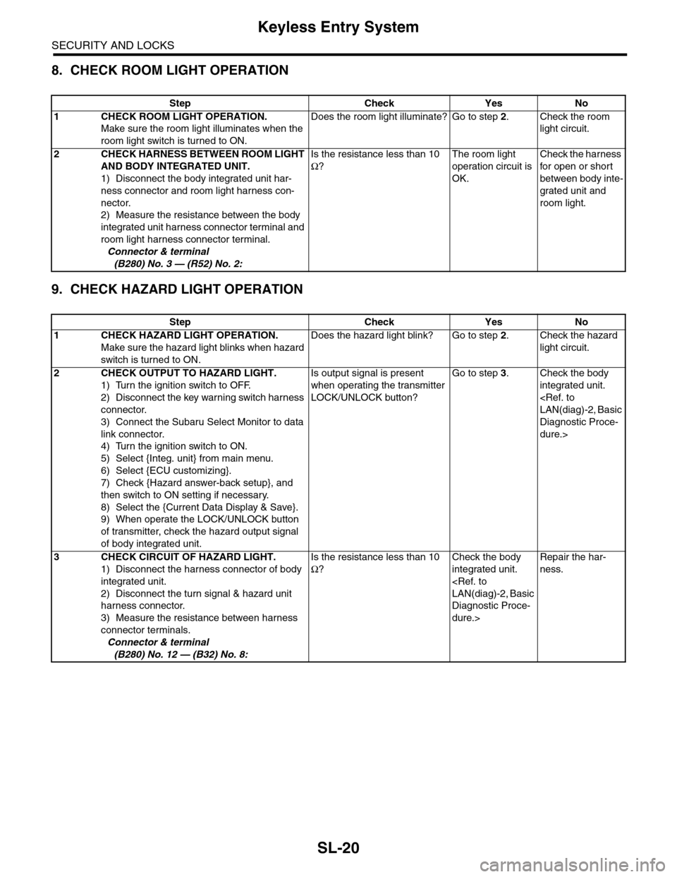
8. CHECK ROOM LIGHT OPERATION
9. CHECK HAZARD LIGHT OPERATION
Step Check Yes No
1CHECK ROOM LIGHT OPERATION.
Make sure the room light illuminates when the
room light switch is turned to ON.
Does the room light illuminate? Go to step 2.Check the room
light circuit.
2CHECK HARNESS BETWEEN ROOM LIGHT
AND BODY INTEGRATED UNIT.
1) Disconnect the body integrated unit har-
ness connector and room light harness con-
nector.
2) Measure the resistance between the body
integrated unit harness connector terminal and
room light harness connector terminal.
Connector & terminal
(B280) No. 3 — (R52) No. 2:
Is the resistance less than 10
Ω?
The room light
operation circuit is
OK.
Check the harness
for open or shor t
between body inte-
grated unit and
room light.
Step Check Yes No
1CHECK HAZARD LIGHT OPERATION.
Make sure the hazard light blinks when hazard
switch is turned to ON.
Does the hazard light blink? Go to step 2.Check the hazard
light circuit.
2CHECK OUTPUT TO HAZARD LIGHT.
1) Turn the ignition switch to OFF.
2) Disconnect the key warning switch harness
connector.
3) Connect the Subaru Select Monitor to data
link connector.
4) Turn the ignition switch to ON.
5) Select {Integ. unit} from main menu.
6) Select {ECU customizing}.
7) Check {Hazard answer-back setup}, and
then switch to ON setting if necessary.
8) Select the {Current Data Display & Save}.
9) When operate the LOCK/UNLOCK button
of transmitter, check the hazard output signal
of body integrated unit.
Is output signal is present
when operating the transmitter
LOCK/UNLOCK button?
Go to step 3.Check the body
integrated unit.
Diagnostic Proce-
dure.>
3CHECK CIRCUIT OF HAZARD LIGHT.
1) Disconnect the harness connector of body
integrated unit.
2) Disconnect the turn signal & hazard unit
harness connector.
3) Measure the resistance between harness
connector terminals.
Connector & terminal
(B280) No. 12 — (B32) No. 8:
Is the resistance less than 10
Ω?
Check the body
integrated unit.
Diagnostic Proce-
dure.>
Repair the har-
ness.
Page 2304 of 2453
WI-20
Power Supply Circuit
WIRING SYSTEM
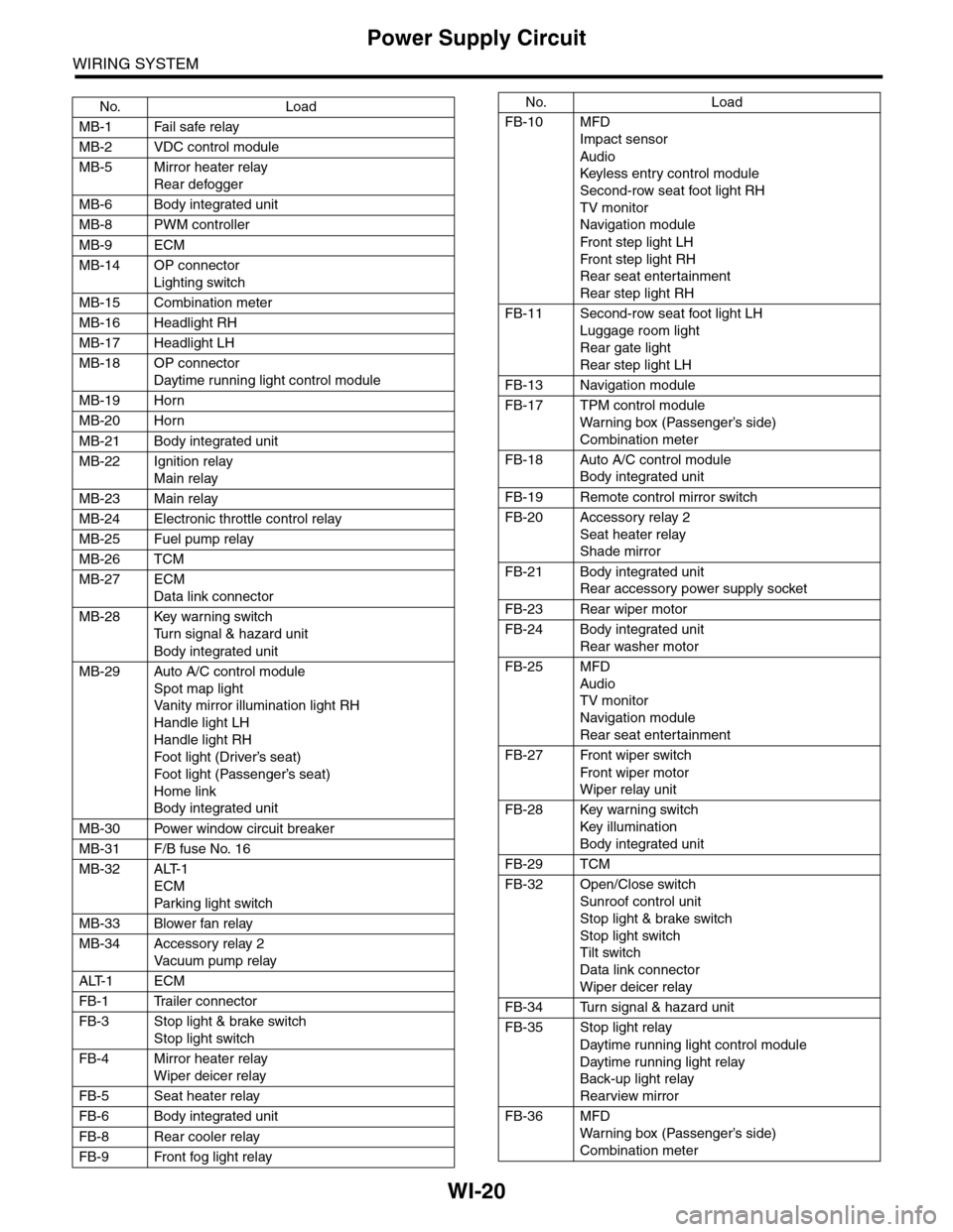
No. Load
MB-1 Fail safe relay
MB-2 VDC control module
MB-5 Mirror heater relay
Rear defogger
MB-6 Body integrated unit
MB-8 PWM controller
MB-9 ECM
MB-14 OP connector
Lighting switch
MB-15 Combination meter
MB-16 Headlight RH
MB-17 Headlight LH
MB-18 OP connector
Daytime running light control module
MB-19 Horn
MB-20 Horn
MB-21 Body integrated unit
MB-22 Ignition relay
Main relay
MB-23 Main relay
MB-24 Electronic throttle control relay
MB-25 Fuel pump relay
MB-26 TCM
MB-27 ECM
Data link connector
MB-28 Key warning switch
Tu r n s i g n a l & h a z a r d u n i t
Body integrated unit
MB-29 Auto A/C control module
Spot map light
Va n i t y m i r r o r i l l u m i n a t i o n l i g h t R H
Handle light LH
Handle light RH
Foot light (Driver’s seat)
Foot light (Passenger’s seat)
Home link
Body integrated unit
MB-30 Power window circuit breaker
MB-31 F/B fuse No. 16
MB-32 ALT-1
ECM
Par king light switch
MB-33 Blower fan relay
MB-34 Accessory relay 2
Va c u u m p u m p r e l ay
ALT-1 ECM
FB-1 Trailer connector
FB-3 Stop light & brake switch
Stop light switch
FB-4 Mirror heater relay
Wiper deicer relay
FB-5 Seat heater relay
FB-6 Body integrated unit
FB-8 Rear cooler relay
FB-9 Front fog light relay
FB-10 MFD
Impact sensor
Audio
Keyless entr y control module
Second-row seat foot light RH
TV monitor
Navigation module
Fr o n t s te p li gh t LH
Fr o n t s te p li gh t RH
Rear seat entertainment
Rear step light RH
FB-11 Second-row seat foot light LH
Luggage room light
Rear gate light
Rear step light LH
FB-13 Navigation module
FB-17 TPM control module
War ning box (Passenger’s side)
Combination meter
FB-18 Auto A/C control module
Body integrated unit
FB-19 Remote control mirror switch
FB-20 Accessory relay 2
Seat heater relay
Shade mirror
FB-21 Body integrated unit
Rear accessory power supply socket
FB-23 Rear wiper motor
FB-24 Body integrated unit
Rear washer motor
FB-25 MFD
Audio
TV monitor
Navigation module
Rear seat entertainment
FB-27 Front wiper switch
Fr o n t wi p er mo t or
Wiper relay unit
FB-28 Key warning switch
Key illumination
Body integrated unit
FB-29 TCM
FB-32 Open/Close switch
Sunroof control unit
Stop light & brake switch
Stop light switch
Tilt switch
Data link connector
Wiper deicer relay
FB-34 Turn signal & hazard unit
FB-35 Stop light relay
Daytime running light control module
Daytime running light relay
Back-up light relay
Rearview mirror
FB-36 MFD
War ning box (Passenger’s side)
Combination meter
No. Load
Page 2306 of 2453
WI-22
Ground Circuit
WIRING SYSTEM
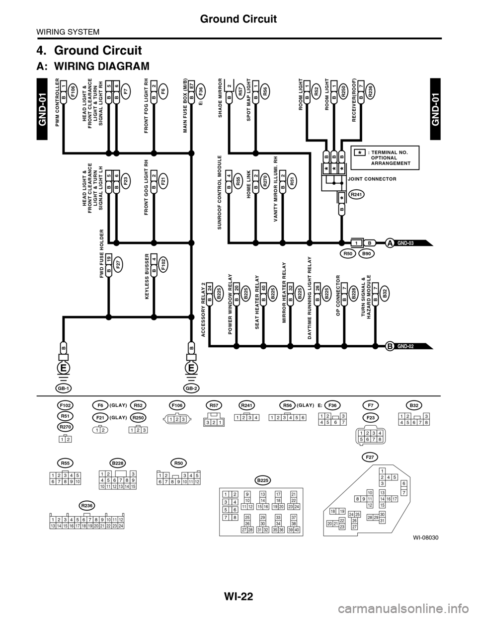
4. Ground Circuit
A: WIRING DIAGRAM
WI-08030
GND-01GND-01
F106B1
PWM CONTROLLER
F6(GLAY)(GLAY)
(GLAY)
F102
R270
F21
F7F6B2
FRONT FOG LIGHT RH
E:
F36B E7
MAIN FUSE BOX (M/B)
R55B4R51B2
VANITY MIROR ILLUMI. RH
R270B2
HOME LINK
R52B1
1
ROOM LIGHT
R250R57B1
ROOM LIGHT
R236B7
RECEIVER(ROOF)SHADE MIRROR
B225B 26
DAYTIME RUNNING LIGHT RELAY
F27B 19FWD FUSE HOLDER
F102B4
KEYLESS BUSSERB225B 24
ACCESSORY RELAY 2
B225B 40
SEAT HEATER RELAY
B225B 20
POWER WINDOW RELAY
B228B7
OP CONNECTOR
B32B7
TURN SIGNAL &HAZARD MODULE
B225B 32
MIRROR HEATER RELAY
GND-02B
GB-1
B
GB-2
B
B
12
12
R52
R250
123
F7
F23
R57
B228
131415
123456789101112
F27
13141516 17
27
24 252620 212223
29303128
89101112
12534
7
6
1918
B225
13141516
17
27
24
2526
20
212223
293031283235
33343738393640
8
9101112
12
534
761918
B32
12345678
SUNROOF CONTROL MODULE
HEAD LIGHT &FRONT CLEARANCELIGHT & TURNSIGNAL LIGHT RH
GND-03A
R51
234510 111678912
R50
F106
123
B A16B5B6
F23F21B2
FRONT GOG LIGHT RH
HEAD LIGHT &FRONT CLEARANCELIGHT & TURNSIGNAL LIGHT LH
B A16B5B6
R56B
SPOT MAP LIGHT
JOINT CONNECTOR
R241
***
*
B90R50
B
B
BBB
1
*: TERMINAL NO. OPTIONAL ARRANGEMENT
123
R56
1234561234567
F36E:
R55
12346789510
R241
1234
R236
123 8910413 14 15 1656711121718192021222324
2
34561278