2009 SUBARU OUTBACK warning light
[x] Cancel search: warning lightPage 98 of 447
2-6Keys and doors
&Locking and unlocking from
the inside
WARNING
Keep all doors locked when you
drive, especially when small chil-
dren are in your vehicle.
Along with the proper use of seat-
belts and child restraints, locking
the doors reduces the chance of
being thrown out of the vehicle in anaccident.
It also helps prevent passengers
from falling out if a door is acciden-
tally opened, and intruders from
unexpectedly opening doors and
entering your vehicle.
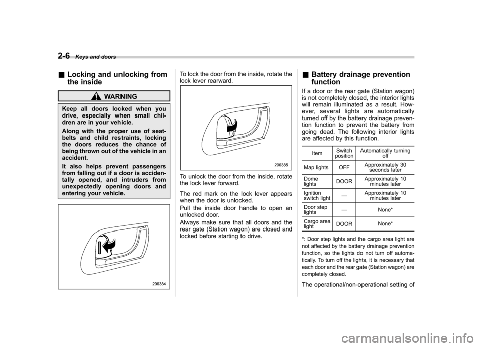
To lock the door from the inside, rotate the
lock lever rearward.
To unlock the door from the inside, rotate
the lock lever forward.
The red mark on the lock lever appears
when the door is unlocked.
Pull the inside door handle to open an
unlocked door.
Always make sure that all doors and the
rear gate (Station wagon) are closed and
locked before starting to drive. &
Battery drainage prevention function
If a door or the rear gate (Station wagon)
is not completely closed, the interior lights
will remain illuminated as a result. How-
ever, several lights are automatically
turned off by the battery drainage preven-
tion function to prevent the battery from
going dead. The following interior lights
are affected by this function.
Item Switch
position Automatically turning
off
Map lights OFF Approximately 30
seconds later
Dome lights DOOR
Approximately 10
minutes later
Ignition
switch light —
Approximately 10
minutes later
Door steplights —
None*
Cargo arealight DOOR
None*
*: Door step lights and the cargo area light are
not affected by the battery drainage prevention
function, so the lights do not turn off automa-
tically. To turn off the lights, it is necessary that
each door and the rear gate (Station wagon) are
completely closed.
The operational/non-operational setting of
Page 113 of 447
a strong impact or multiple impacts by
sounding the horn and flashing the turn
signal lights, both lasting approximately 30seconds.
If you desire, your SUBARU dealer can
connect them and set them for activation
or deactivation. NOTE .The shock sensors are not always
able to sense impacts caused by break-
ing in, and cannot sense an impact that
does not cause vibration (such as
breaking the glass using a rescuehammer).. The shock sensors may sense vi-
bration like those shown in the follow-
ing and trigger the alarm system.
Select the settings of the alarm system
and shock sensors appropriately de-
pending on where you usually park
your vehicle.Example:
Vibration from construction site
Vibration in multistory car park
Vibration from trains
. You can have the sensitivity of the
shock sensors adjusted to your pre-
ference by your SUBARU dealer. Child safety locks
WARNING
Always use the child safety lock
whenever a child rides in the rear
seat. Serious injury could result if a
child accidentally opened the door
and fell out.
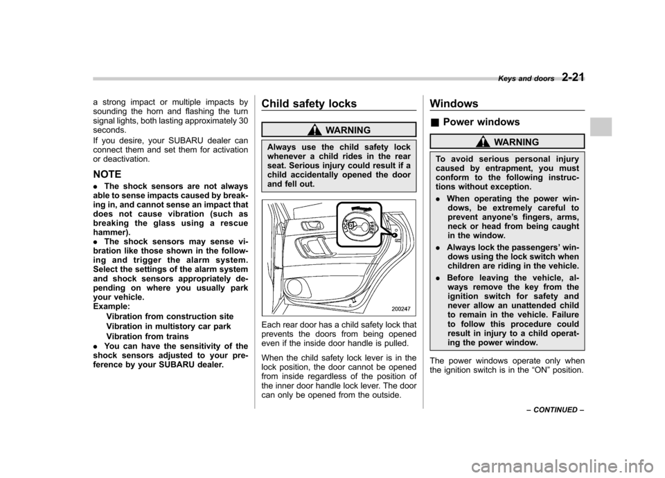
Each rear door has a child safety lock that
prevents the doors from being opened
even if the inside door handle is pulled.
When the child safety lock lever is in the
lock position, the door cannot be opened
from inside regardless of the position of
the inner door handle lock lever. The door
can only be opened from the outside. Windows &
Power windows
WARNING
To avoid serious personal injury
caused by entrapment, you must
conform to the following instruc-
tions without exception. . When operating the power win-
dows, be extremely careful to
prevent anyone ’s fingers, arms,
neck or head from being caught
in the window.
. Always lock the passengers ’win-
dows using the lock switch when
children are riding in the vehicle.
. Before leaving the vehicle, al-
ways remove the key from the
ignition switch for safety and
never allow an unattended child
to remain in the vehicle. Failure
to follow this procedure could
result in injury to a child operat-
ing the power window.
The power windows operate only when
the ignition switch is in the “ON ”position.
Keys and doors
2-21
– CONTINUED –
Page 116 of 447
2-24Keys and doors
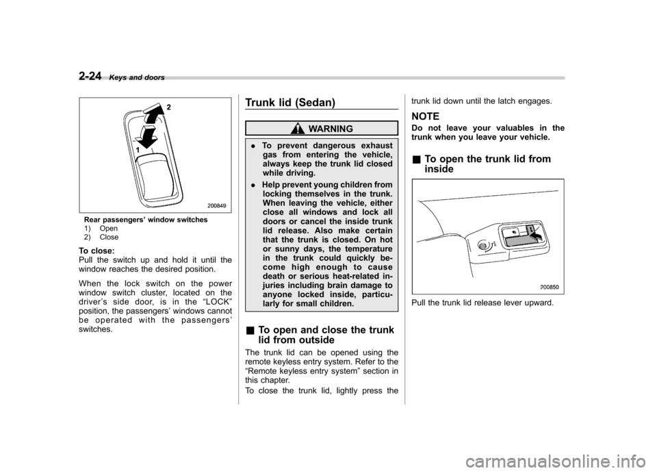
Rear passengers ’window switches
1) Open
2) Close
To close:
Pull the switch up and hold it until the
window reaches the desired position.
When the lock switch on the power
window switch cluster, located on thedriver ’s side door, is in the “LOCK ”
position, the passengers ’windows cannot
be operated with the passengers ’
switches. Trunk lid (Sedan)
WARNING
. To prevent dangerous exhaust
gas from entering the vehicle,
always keep the trunk lid closed
while driving.
. Help prevent young children from
locking themselves in the trunk.
When leaving the vehicle, either
close all windows and lock all
doors or cancel the inside trunk
lid release. Also make certain
that the trunk is closed. On hot
or sunny days, the temperature
in the trunk could quickly be-
come high enough to cause
death or serious heat-related in-
juries including brain damage to
anyone locked inside, particu-
larly for small children.
& To open and close the trunk
lid from outside
The trunk lid can be opened using the
remote keyless entry system. Refer to the“ Remote keyless entry system ”section in
this chapter.
To close the trunk lid, lightly press the trunk lid down until the latch engages. NOTE
Do not leave your valuables in the
trunk when you leave your vehicle. &
To open the trunk lid from inside
Pull the trunk lid release lever upward.
Page 117 of 447
&To lock and unlock the trunk
lid release lever
When you entrust your vehicle key to
another person, you can lock the trunk lid
release lever to prevent luggage in the
trunk from being stolen. To lock the trunk
lid release lever, insert the master key or
submaster key into the key cylinder at the
rear of the release lever and turn it
counterclockwise. To unlock the trunk lid
release lever, turn the key clockwise. &Internal trunk lid release handle
The internal trunk lid release handle is a
device designed to open the trunk lid from
inside the trunk. In the event children or
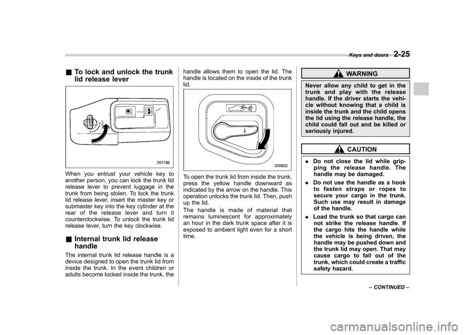
adults become locked inside the trunk, the handle allows them to open the lid. The
handle is located on the inside of the trunklid.To open the trunk lid from inside the trunk,
press the yellow handle downward as
indicated by the arrow on the handle. This
operation unlocks the trunk lid. Then, push
up the lid.
The handle is made of material that
remains luminescent for approximately
an hour in the dark trunk space after it is
exposed to ambient light even for a shorttime.
WARNING
Never allow any child to get in the
trunk and play with the release
handle. If the driver starts the vehi-
cle without knowing that a child is
inside the trunk and the child opens
the lid using the release handle, the
child could fall out and be killed or
seriously injured.
CAUTION
. Do not close the lid while grip-
ping the release handle. The
handle may be damaged.
. Do not use the handle as a hook
to fasten straps or ropes to
secure your cargo in the trunk.
Such use may result in damage
of the handle.
. Load the trunk so that cargo can
not strike the release handle. If
the cargo hits the handle while
the vehicle is being driven, the
handle may be pushed down and
the trunk lid may open. That may
cause cargo to fall out of the
trunk, which could create a traffic
safety hazard. Keys and doors
2-25
– CONTINUED –
Page 124 of 447

Ignition switch..................................................... 3-3
LOCK .................................................................. 3-3
Acc..................................................................... 3-4
ON...................................................................... 3-4
START ................................................................ 3-4
Key reminder chime ............................................ 3-5
Ignition switch light ............................................. 3-5
Hazard warning flasher ....................................... 3-5
Meters and gauges (vehicle with SI-DRIVE) ...... 3-5
Combination meter illumination ........................... 3-5
Speedometer ....................................................... 3-6
Tachometer ......................................................... 3-6
Fuel gauge .......................................................... 3-6
Temperature gauge ............................................. 3-7
ECO gauge ......................................................... 3-8
Multi-information display (vehicle with SI-DRIVE) .................................... 3-9
Display ............................................................... 3-9
Operation switch ................................................. 3-9
Odometer and trip meter .................................... 3-10
Current and average fuel consumption ............... 3-11
Outside temperature and journey time ................ 3-12
Driving range on remaining fuel .......................... 3-14
Clock (vehicle with genuine SUBARU navigation system) ............................................................ 3-15
SI-DRIVE display ................................................ 3-15
Meter settings .................................................... 3-15
Warning messages and driver ’s information ........ 3-20
Meters and gauges (vehicle without SI-DRIVE) .............................. 3-24
Combination meter illumination .......................... 3-24 Canceling the function for meter/gauge needle
movement upon turning on the ignition switch ............................................................. 3-24
Speedometer ..................................................... 3-24
Odometer .......................................................... 3-25
Double trip meter ............................................... 3-25
Tachometer ....................................................... 3-26
Fuel gauge ........................................................ 3-26
Temperature gauge ............................................ 3-27
Warning and indicator lights ............................. 3-28
Seatbelt warning light and chime ....................... 3-29
SRS airbag system warning light ........................ 3-30
Front passenger ’s frontal airbag ON and OFF
indicators ........................................................ 3-31
CHECK ENGINE warning light/Malfunction indicator lamp ................................................. 3-31
Charge warning light .......................................... 3-32
Oil pressure warning light .................................. 3-32
AT OIL TEMP warning light (AT models) .............. 3-33
Low tire pressure warning light (U.S.-spec. models) ........................................................... 3-33
ABS warning light .............................................. 3-34
Brake system warning light ................................ 3-35
Low fuel warning light ....................................... 3-36
Door open warning light .................................... 3-36
All-Wheel Drive warning light (AT models) ..... ..... 3-36
Vehicle Dynamics Control operation indicator light (if equipped). ............................................ 3-37
Vehicle Dynamics Control warning light (if equipped)/Vehicle Dynamics Control OFF
indicator light (if equipped) .............................. 3-37
Security indicator light ....................................... 3-38
Instruments and controls
3
Page 126 of 447
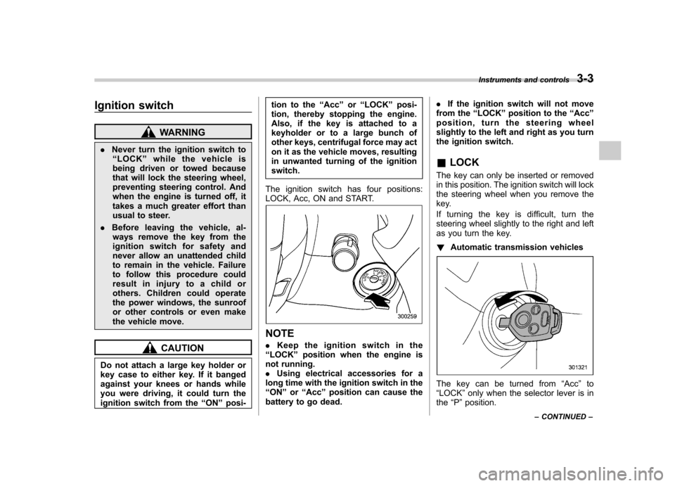
Ignition switch
WARNING
. Never turn the ignition switch to
“ LOCK ”while the vehicle is
being driven or towed because
that will lock the steering wheel,
preventing steering control. And
when the engine is turned off, it
takes a much greater effort than
usual to steer.
. Before leaving the vehicle, al-
ways remove the key from the
ignition switch for safety and
never allow an unattended child
to remain in the vehicle. Failure
to follow this procedure could
result in injury to a child or
others. Children could operate
the power windows, the sunroof
or other controls or even make
the vehicle move.
CAUTION
Do not attach a large key holder or
key case to either key. If it banged
against your knees or hands while
you were driving, it could turn the
ignition switch from the “ON ”posi- tion to the
“Acc ”or “LOCK ”posi-
tion, thereby stopping the engine.
Also, if the key is attached to a
keyholder or to a large bunch of
other keys, centrifugal force may act
on it as the vehicle moves, resulting
in unwanted turning of the ignitionswitch.
The ignition switch has four positions:
LOCK, Acc, ON and START.
NOTE . Keep the ignition switch in the
“ LOCK ”position when the engine is
not running. . Using electrical accessories for a
long time with the ignition switch in the“ ON ”or “Acc ”position can cause the
battery to go dead. .
If the ignition switch will not move
from the “LOCK ”position to the “Acc ”
position, turn the steering wheel
slightly to the left and right as you turn
the ignition switch. & LOCK
The key can only be inserted or removed
in this position. The ignition switch will lock
the steering wheel when you remove the
key.
If turning the key is difficult, turn the
steering wheel slightly to the right and left
as you turn the key. ! Automatic transmission vehicles
The key can be turned from “Acc ”to
“ LOCK ”only when the selector lever is in
the “P ”position. Instruments and controls
3-3
– CONTINUED –
Page 128 of 447

&Key reminder chime
The reminder chime sounds when the driver ’s door opens and the key is in the
“ LOCK ”or “Acc ”positions. The chime
stops when the key is removed from the
ignition switch. & Ignition switch light
For easy access to the ignition switch in
the dark, the ignition switch light illumi-
nates when any of the doors are opened.
The light remains on for a several seconds
and gradually goes out after all doors are
closed or if the key is inserted in the
ignition switch. Hazard warning flasher
The hazard warning flasher is used to
warn other drivers when you have to park
your vehicle under emergency conditions.
The hazard warning flasher works with the
ignition switch in any position.
To turn on the hazard warning flasher,
push the hazard warning button on the
instrument panel. To turn off the flasher,
push the button again. NOTE
When the hazard warning flasher is on,
the turn signals do not work.Meters and gauges (vehicle
with SI-DRIVE) NOTE
Liquid-crystal displays are used in
some of the meters and gauges in the
combination meter. You will find their
indications hard to see if you wear
polarized glasses. &
Combination meter illumina- tion
When the ignition switch is turned to the “ ON ”position, the various parts of the
combination meter are illuminated in the
following sequence:
1. Meter needles, gauge needles and
multi-information display light up.
2. Meter needles and gauge needles
each show MAX position.
3. Meter needles and gauge needles
each show MIN position.
4. Dials in meters and gauges light up.
5. Regular illumination (for driving) be- gins.
NOTE
The above sequence of operations may
not take place if you quickly turn the Instruments and controls
3-5
– CONTINUED –
Page 130 of 447

NOTE
You will see the“”sign in the fuel
gauge.
This indicates that the fuel filler door
(lid) is located on the right side of thevehicle. !
Low fuel warning light1) Low fuel warning light
The low fuel warning light illuminates
when the tank is nearly empty [Approxi-
mately 2.6 US gal (10 liters, 2.2 lmp gal)].
It only operates when the ignition switch is
in the “ON ”position.
NOTE
This light does not go out unless the
tank is replenished up to an internal
fuel quantity of approximately 4.0 US
gal (15 liters, 3.3 lmp gal).
CAUTION
Promptly put fuel in the tank when-
ever the low fuel warning light
illuminates. Engine misfires as a
result of an empty tank could cause
damage to the engine.
& Temperature gauge
1) Normal operating range
2) S# PREP indicator light
The temperature gauge shows engine
coolant temperature when the ignition
switch is in the “ON ”position.
The coolant temperature will vary in
accordance with the outside temperature
and driving conditions. Instruments and controls
3-7
– CONTINUED –