2009 SUBARU LEGACY fog light
[x] Cancel search: fog lightPage 191 of 447

!Temperature control dial
Driver ’s side
Passenger ’s side
It is possible to make separate tempera-
ture settings for the driver ’s side and passenger
’s side. Each temperature
setting is shown on the display. With the
dial set at your desired temperature, the
system automatically adjusts the tempera-
ture of air supplied from the outlets such
that the desired temperature is achieved
and maintained.
If the dial is turned fully counterclockwise,
the system gives maximum cooling per-
formance. If the dial is turned fully clock-
wise, the system gives maximum heatingperformance. !
– Defroster button
To defrost or dehumidify the windshield
and front door windows, push the defros-
ter button “
”. When the “”button is
pushed, outside air is drawn into the
passenger compartment, air flow is direc-
ted towards the windshield and front door windows, and the indicator light on the
button illuminates.
After eliminating the fogging from the
windshield, return the climate control
system to the AUTO mode by pushingthe
“AUTO ”button or turn off by pushing
the “OFF ”button.
Alternatively, push the “
”button again
to return the system to the setting that was
selected before you activated the defros-
ter. ! Fan speed control button
The fan speed control button has 6
different fan speed positions.
The fan speed is shown by the display. Climate control
4-9
– CONTINUED –
Page 192 of 447

4-10Climate control
! A/C –Air conditioner button
If the windshield starts to fog when the
climate control system is operated in the
AUTO mode, push the air conditionerbutton “A/C ”to defog and dehumidify.
When this button is pushed, the air
conditioner compressor turns on and the
indicator light “A/C ”on the display illumi-
nates. After eliminating the fogging from
the windshield, set the system back to the
AUTO mode by pushing the “AUTO ”
button.
NOTE
The air conditioner compressor does
not operate when the outside air tem-
perature is below 32 8F(0 8C). !
Air flow mode selection buttonSelect the desired air flow mode by
pushing the air flow mode selection
button. The selected air flow mode is
shown by the display.
(Ventilation): Air flows through the
instrument panel outlets.
(Bi-level): Air flows through the instru-
ment panel outlets and the foot outlets.
(Heat): Air flows through the instrument
panel outlets, the foot outlets, and some
through the windshield defroster outlets.
(Heat-def): Air flows through the instru-
ment panel outlets, the windshield defros-
ter outlets, and the foot outlets. !
Air inlet selection button
Select air flow by pushing the air inlet
selection button “/”.
The selected air inlet setting is shown on
the control panel.
(Recirculation): Interior air recirculates
inside the passenger compartment. Use
this position when quickly cooling down
the passenger compartment or to prevent
outside air from entering the passenger
compartment. When the recirculation
mode is selected, a “
”indicator light
appears on the display.
(Outside air): Outside air is drawn into
the passenger compartment. When the
climate control system is operated in the“ AUTO ”mode, this position is selected
automatically. (There is one exception:
Page 193 of 447

When the temperature control dial is
turned fully counterclockwise, the recircu-
lation mode is automatically selected.)
When the outside air mode is selected, a“
”indicator light appears on the dis-
play.
WARNING
Continued operation in the “
”
position may fog up the windows.
Switch to the “
”position as soon
as the outside dusty condition clears.
NOTE
When driving on a dusty road or behind
a vehicle that emits unpleasant exhaust
gases, set the air inlet selection button
to the “
”position.
From time to time, return the air inlet
selection button to the “
”position
to draw outside air into the passenger compartment. &
Temperature sensors
1) Solar sensor
2) Interior air temperature sensor
The automatic climate control system
employs several sensors. These sensors
are delicate. If they are treated incorrectly
and become damaged, the system may
not be able to control the interior tempera-
ture correctly. To avoid damaging the
sensors, observe the following precau-tions: – Do not subject the sensors to impact.
– Keep water away from the sensors.
– Do not cover the sensors.
The sensors are located as follows:– Solar sensor: beside windshield
defroster grille –
Interior air temperature sensor: on the
side of the driver-side part of the center panel – Outside temperature sensor: behind
front grille. Climate control
4-11
Page 339 of 447

9-14In case of emergency
&Towing and tie-down hooks
The towing hooks should be used only in
an emergency (e.g., to free a stuck vehicle
from mud, sand or snow).
CAUTION
. Use only the specified towing
hooks and tie-down hooks. Never
use suspension parts or other
parts of the body for towing or
tie-down purposes.
. Never use the tie-down hook
closest to the muffler under the
vehicle for towing purposes.
. To prevent deformation to the
bumper and the towing hook, do
not apply excessive lateral load
to the towing hooks.
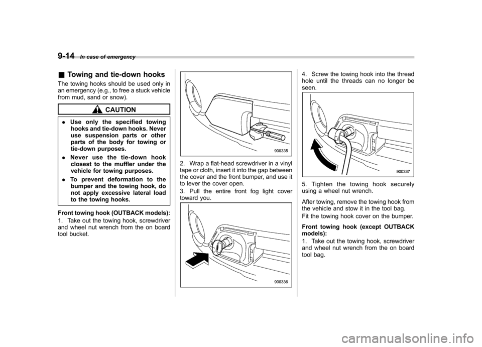
Front towing hook (OUTBACK models):
1. Take out the towing hook, screwdriver
and wheel nut wrench from the on board
tool bucket.
2. Wrap a flat-head screwdriver in a vinyl
tape or cloth, insert it into the gap between
the cover and the front bumper, and use it
to lever the cover open.
3. Pull the entire front fog light cover
toward you.
4. Screw the towing hook into the thread
hole until the threads can no longer beseen.
5. Tighten the towing hook securely
using a wheel nut wrench.
After towing, remove the towing hook from
the vehicle and stow it in the tool bag.
Fit the towing hook cover on the bumper.
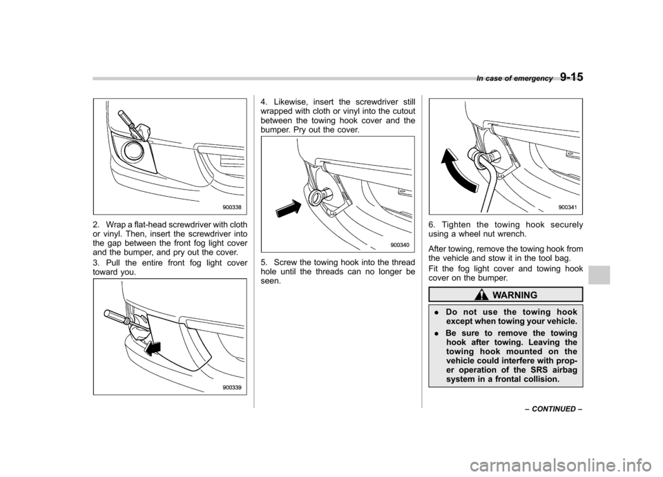
Front towing hook (except OUTBACK models):
1. Take out the towing hook, screwdriver
and wheel nut wrench from the on board
tool bag.
Page 340 of 447

2. Wrap a flat-head screwdriver with cloth
or vinyl. Then, insert the screwdriver into
the gap between the front fog light cover
and the bumper, and pry out the cover.
3. Pull the entire front fog light cover
toward you.
4. Likewise, insert the screwdriver still
wrapped with cloth or vinyl into the cutout
between the towing hook cover and the
bumper. Pry out the cover.
5. Screw the towing hook into the thread
hole until the threads can no longer beseen.
6. Tighten the towing hook securely
using a wheel nut wrench.
After towing, remove the towing hook from
the vehicle and stow it in the tool bag.
Fit the fog light cover and towing hook
cover on the bumper.
WARNING
. Do not use the towing hook
except when towing your vehicle.
. Be sure to remove the towing
hook after towing. Leaving the
towing hook mounted on the
vehicle could interfere with prop-
er operation of the SRS airbag
system in a frontal collision. In case of emergency
9-15
– CONTINUED –
Page 352 of 447

Maintenance and serviceTire pressure monitoring system (TPMS)(if equipped) ................................................... 11-34
Tire inspection ................................................. 11-35
Tire pressures and wear ................................... 11-36
Wheel balance .................................................. 11-38
Wear indicators ................................................ 11-38
Tire rotation direction mark .............................. 11-38
Tire rotation ..................................................... 11-39
Tire replacement .............................................. 11-39
Wheel replacement ........................................... 11-40
Aluminum wheels ............................................. 11-40
Windshield washer fluid .................................. 11-41
Replacement of wiper blades .......................... 11-42
Windshield wiper blade assembly ..................... 11-42
Windshield wiper blade rubber ......................... 11-43
Rear window wiper blade assembly .................. 11-44
Rear window wiper blade rubber ....................... 11-45
Battery. .............................................................. 11-46 Fuses
................................................................ 11-47
Main fuse .......................................................... 11-49
Installation of accessories .............................. 11-49
Replacing bulbs ............................................... 11-50
Headlight ......................................................... 11-51
Front turn signal/Parking and front side marker light .............................................................. 11-53
Front fog light (if equipped) .............................. 11-53
Rear combination lights ................................... 11-53
Back-up light (Station wagon) .......................... 11-56
License plate light ........................................... 11-56
Dome light ....................................................... 11-57
Map light ......................................................... 11-57
Vanity mirror light ............................................ 11-58
Door step light ................................................. 11-58
Cargo area light (Station wagon) ... ................... 11-59
Trunk light (Sedan) .......................................... 11-59
High mount stop light (Sedan) .......................... 11-59
Page 399 of 447

Main fuse
Main fuse box
The main fuses are designed to melt
during an overload to prevent damage to
the wiring harness and electrical equip-
ment. Check the main fuses if any
electrical component fails to operate (ex-
cept the starter motor) and other fuses are
good. A melted main fuse must be
replaced. Use only replacements with the
same specified rating as the melted main
fuse. If a main fuse blows after it is
replaced, have the electrical system
checked by your nearest SUBARU dealer. Installation of accessories
Always consult your SUBARU dealer
before installing fog lights or any other
electrical equipment in your vehicle. Such
accessories may cause the electronic
system to malfunction if they are incor-
rectly installed or if they are not suited for
the vehicle.
Maintenance and service
11-49
Page 401 of 447

Wattage Bulb No.
1) High beam headlight 12V-60W 9005 (HB3) 2) Low beam headlight 12V-55W H7
3) Front turn signal/Parking and front side marker light 12V-27/8W 3457A
4) Map light 12V-8W–
5) Dome light 12V-8W–
6) Door step light 12V-3W–
7) Vanity mirror light 12V-3W–
8) Front fog light 12V-51W 9006 (HB4)
9) Trunk light (Sedan) 12V-5W 168 (W5W)
10) High mount stop light (Sedan) 12V-21W (W21W)
11 ) Rear turn signal light (Sedan) 12V-21W (WY21W)
12) Back-up light (Sedan) 12V-16W 921
13) Brake/Tail and rear side marker light (Sedan) 12V-21/5W (W21/5W)
14) Cargo area light (Station wagon) 12V-13W –
15) Brake/Tail light (Station wagon) 12V-21/5W (W21/5W)
16) Rear side marker light (Station wagon) 12V-5W 168 (W5W)
17) Rear turn signal light (Station wagon) 12V-21W (WY21W)
18) Back-up light (Station wagon) 12V-16W 921
19) Licence plate light 12V-5W168 (W5W)CAUTION
Replace any bulb only with a new
bulb of the specified wattage. Using
a bulb of different wattage could
result in a fire.
& Headlight
CAUTION
Halogen headlight bulbs become
very hot while in use. If you touch
the bulb surface with bare hands or
greasy gloves, fingerprints or
grease on the bulb surface will
develop into hot spots, causing the
bulb to break. If there are finger-
prints or grease on the bulb surface,
wipe them away with a soft cloth
moistened with alcohol.
NOTE . If headlight aiming is required, con-
sult your SUBARU dealer for proper
adjustment of the headlight aim.. It may be difficult to replace the
bulbs. Have the bulbs replaced by your
SUBARU dealer if necessary. Maintenance and service
11-51
– CONTINUED –