2009 SUBARU FORESTER illumination
[x] Cancel search: illuminationPage 135 of 384
3-24Instruments and controls
Light control switch
The light control switch only operates
when the ignition key is inserted into the
ignition switch.
Regardless of the position of the light
control switch, the illuminated lights are
turned off when the ignition key is
removed from the ignition switch. NOTE .Even if the ignition key is removed
from the ignition switch, the lights can
be illuminated by operating the light
control switch position from “OFF ”to
“
” and/or “”.
. If the driver ’s door is opened while
the lights are illuminated and the igni-
tion key is removed from the ignition
switch, the chirp sound informs the
driver that the lights are illuminated.
CAUTION
. Use of any lights for a long period
of time while the engine is not
running can cause the battery todischarge.
. Before leaving the vehicle, make
sure that the light control switch
is turned to the “OFF ”position. If
the vehicle is left unattended for a long time with the light control
switch set to a position otherthan
“OFF ”, the battery may be
discharged. &
Headlights
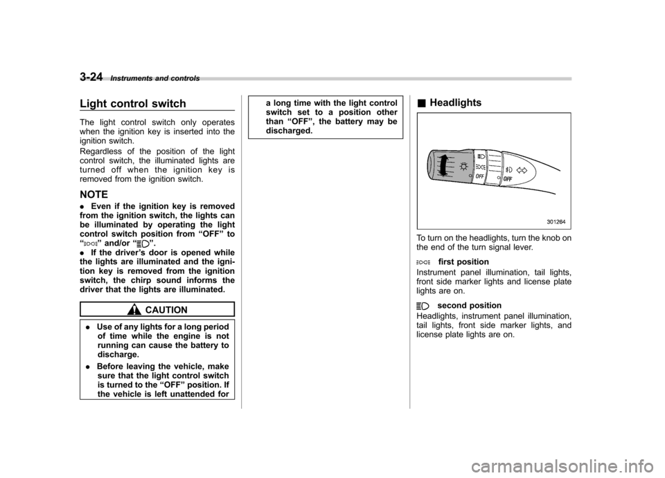
To turn on the headlights, turn the knob on
the end of the turn signal lever.
first position
Instrument panel illumination, tail lights,
front side marker lights and license plate
lights are on.
second position
Headlights, instrument panel illumination,
tail lights, front side marker lights, and
license plate lights are on.
Page 136 of 384
&High/low beam change (dim- mer)
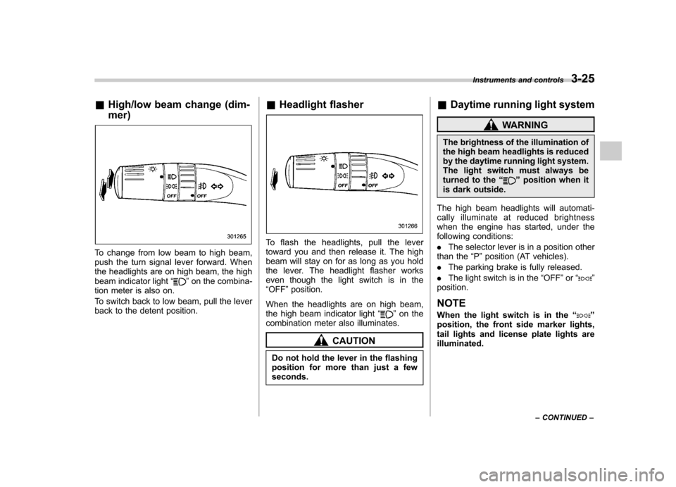
To change from low beam to high beam,
push the turn signal lever forward. When
the headlights are on high beam, the high
beam indicator light “
”on the combina-
tion meter is also on.
To switch back to low beam, pull the lever
back to the detent position. &
Headlight flasher
To flash the headlights, pull the lever
toward you and then release it. The high
beam will stay on for as long as you hold
the lever. The headlight flasher works
even though the light switch is in the“OFF ”position.
When the headlights are on high beam,
the high beam indicator light “
”on the
combination meter also illuminates.
CAUTION
Do not hold the lever in the flashing
position for more than just a fewseconds. &
Daytime running light system
WARNING
The brightness of the illumination of
the high beam headlights is reduced
by the daytime running light system.
The light switch must always be
turned to the “
”position when it
is dark outside.
The high beam headlights will automati-
cally illuminate at reduced brightness
when the engine has started, under the
following conditions: . The selector lever is in a position other
than the “P ”position (AT vehicles).
. The parking brake is fully released.
. The light switch is in the “OFF ”or “
”
position.
NOTE
When the light switch is in the “
”
position, the front side marker lights,
tail lights and license plate lights areilluminated. Instruments and controls
3-25
– CONTINUED –
Page 137 of 384
3-26Instruments and controls
&Automatic headlight beam
leveler (vehicles with HID headlights)
The HID headlights generate more light
than conventional halogen headlights.
Therefore a driver of an oncoming vehicle
may experience too much glare when your
headlight beam height adjustment is high
due to the vehicle carrying heavy load.
The automatic headlight beam leveler
adjusts the headlight beam height auto-
matically and optimally according to the
load being carried by the vehicle. Turn signal lever
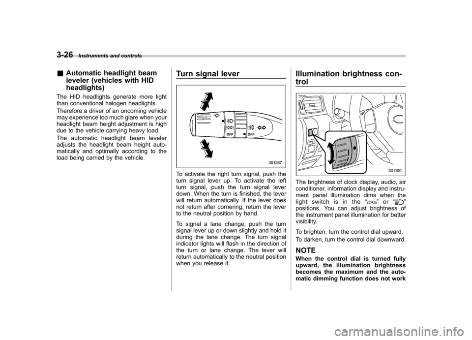
To activate the right turn signal, push the
turn signal lever up. To activate the left
turn signal, push the turn signal lever
down. When the turn is finished, the lever
will return automatically. If the lever does
not return after cornering, return the lever
to the neutral position by hand.
To signal a lane change, push the turn
signal lever up or down slightly and hold it
during the lane change. The turn signal
indicator lights will flash in the direction of
the turn or lane change. The lever will
return automatically to the neutral position
when you release it.Illumination brightness con- trol
The brightness of clock display, audio, air
conditioner, information display and instru-
ment panel illumination dims when the
light switch is in the
“
”or “”
positions. You can adjust brightness of
the instrument panel illumination for better
visibility.
To brighten, turn the control dial upward.
To darken, turn the control dial downward.
NOTE
When the control dial is turned fully
upward, the illumination brightness
becomes the maximum and the auto-
matic dimming function does not work
Page 215 of 384

7-6Starting and operating
State emission testing (U.S. only)
At state inspection time, remember to
tell your inspection or service station in
advance not to place your SUBARU
AWD vehicle on a two-wheel dynam-
ometer. Otherwise, serious transmis-
sion damage will result.
Some states have started using dynam-
ometers in their state inspection programs
in order to meet their obligation under
federal law to implement stricter vehicle
emission standards to reduce air pollution
from vehicles. A dynamometer is a tread-
mill or roller-like testing device that allows
your vehicle ’s wheels to turn while the
vehicle remains in one place. Depending
on the severity of a state ’s air pollution
problems, the states must adopt either a“ basic ”or “enhanced ”vehicle emission
inspection test. Normally, a portion of the
basic emission test consists of an emis-
sion inspector inserting an analyzer probe
into the exhaust pipe of an idling vehicle
for a short period of time. States with more
severe air pollution problems are required
to adopt an enhanced vehicle emission
test. This test simulates actual driving
conditions on a dynamometer and permits
more accurate measurement of tailpipe
emitted pollution than the basic emission test.
The U.S. Environmental Protection
Agency (EPA) and states using two-wheel
dynamometers in their emission testing
programs have
EXEMPTEDSUBARU
AWD vehicles from the portion of the
testing program that involves a two-wheel
dynamometer.
There are some states that use four-wheel
dynamometers in their testing programs.
When properly used, that equipment will
not damage an AWD SUBARU vehicle.
Under no circumstances should the rear
wheels be jacked off the ground, nor
should the driveshaft be disconnected for
state emission testing.
WARNING
Testing of an All-Wheel Drive vehicle
must NEVER be performed on a
single two-wheel dynamometer. At-
tempting to do so will result in
uncontrolled vehicle movement and
may cause an accident or injuries to
persons nearby.
CAUTION
Resultant vehicle damage due to
improper testing is not covered
under the SUBARU Limited War-
ranty and is the responsibility of
the state inspection program or its
contractors or licensees.
The EPA has issued regulations for
inspecting the On-Board Diagnostic
(OBD) system as part of the state emis-
sions inspection. The OBD system is
designed to detect engine and transmis-
sion problems that might cause vehicle
emissions to exceed allowable limits.
These inspections apply to all 1996 model
year and newer passenger cars and light
trucks. Over 30 states plus the District of
Columbia have implemented the OBD
system inspection. . The inspection of the OBD system
consists of a visual operational check of the “CHECK ENGINE ”warning light/mal-
function indicator lamp (MIL) and an
examination of the OBD system with an
electronic scan tool while the engine isrunning. . Avehicle
passes the OBD system
inspection if proper illumination of the “ CHECK ENGINE ”warning light/MIL is
observed, there are nostored diagnostic
Page 235 of 384
7-26Starting and operating
Vehicle Dynamics Control system
WARNING
Always use the utmost care in driving –overconfidence because
you are driving with a Vehicle Dy-
namics Control system equipped
vehicle could easily lead to a ser-
ious accident.
CAUTION
. Even if your vehicle is equipped
with Vehicle Dynamics Control,
winter tires or snow chains
should be used when driving on
snow-covered or icy roads; in
addition, vehicle speed should
be reduced considerably. Simply
having a Vehicle Dynamics Con-
trol system does not guarantee
that the vehicle will be able to
avoid accidents in any situation.
. Activation of the Vehicle Dy-
namics Control system is an
indication that the road being
travelled on has a slippery sur-
face; since having Vehicle Dy-
namics Control is no guarantee that full vehicle control will be
maintained at all times and under
all conditions, its activation
should be seen as a sign that
the speed of the vehicle should
be reduced considerably.
. Whenever suspension compo-
nents, steering components, or
an axle are removed from a
vehicle equipped with Vehicle
Dynamics Control, have an
authorized SUBARU dealer per-
form an inspection of that sys-tem.
. The following precautions should
be observed in order to ensure
that the Vehicle Dynamics Con-
trol system is operating properly: – All four wheels should be
fitted with tires of the same
size, type, and brand. Further-
more, the amount of wear
should be the same for all
four tires.
– Keep the tire pressure at the
proper level as shown on the
vehicle placard attached to
the driver ’s side door pillar.
– Use only the specified tem-
porary spare tire to replace a
flat tire. With a temporary spare tire, the effectiveness of
the Vehicle Dynamics Control
system is reduced and this
should be taken into account
when driving the vehicle in
such a condition.
In the event of wheelspin and/or skidding
on a slippery road surface and/or during
cornering and/or an evasive maneuver,
the Vehicle Dynamics Control system
adjusts the engine ’s output and the
wheels ’respective braking forces to help
maintain traction and directional control. . Traction Control Function
The traction control function is designed to
prevent spinning of the driving wheels on
slippery road surfaces, thereby helping to
maintain traction and directional control.
Activation of this function is shown by
steady illumination of the Vehicle Dy-
namics Control operation indicator light. . Skid Suppression Function
The skid suppression function is designed
to help maintain directional stability by
suppressing the wheels ’tendency to slide
sideways during steering operations. Acti-
vation of this function is shown by flashing
of the Vehicle Dynamics Control operation
indicator light.
Page 327 of 384
![SUBARU FORESTER 2009 SH / 3.G Owners Manual 11-32Maintenance and service
Outside
temperature Adjusted pressure
[psi (kPa, kgf/cm2)]
front rear
30 8F( �18C) 35
(240, 2.4) 33
(230, 2.3)
10 8F( �12 8C) 37
(255, 2.55) 35
(240, 2.4)
� 10 8F( �23 8C) SUBARU FORESTER 2009 SH / 3.G Owners Manual 11-32Maintenance and service
Outside
temperature Adjusted pressure
[psi (kPa, kgf/cm2)]
front rear
30 8F( �18C) 35
(240, 2.4) 33
(230, 2.3)
10 8F( �12 8C) 37
(255, 2.55) 35
(240, 2.4)
� 10 8F( �23 8C)](/manual-img/17/7205/w960_7205-326.png)
11-32Maintenance and service
Outside
temperature Adjusted pressure
[psi (kPa, kgf/cm2)]
front rear
30 8F( �18C) 35
(240, 2.4) 33
(230, 2.3)
10 8F( �12 8C) 37
(255, 2.55) 35
(240, 2.4)
� 10 8F( �23 8C) 39
(270, 2.7) 37
(255, 2.55)
If the low tire pressure warning light
illuminates when you drive the vehicle in
cold outside air after adjusting the tire
pressures in a warm garage, re-adjust the
tire pressures using the method described
above. Then, increase the vehicle speed
to at least 20 mph (32 km/h) and check to
see that the low tire pressure warning light
turns off a few minutes later. If the low tire
pressure warning light does not turn off,
the tire pressure monitoring system may
not be functioning normally. In this event,
go to a SUBARU dealer to have the
system inspected as soon as possible.
While the vehicle is driven, friction be-
tween tires and the road surface causes
the tires to warm up. After illumination of
the low tire pressure warning light, any
increase in the tire pressures caused by
an increase in the outside air temperature
or by an increase in the temperature in the tires can cause the low tire pressure
warning light to turn off.
System resetting is necessary when the
wheels are changed (for example, a
switch to snow tires) and new TPMS
valves are installed on the newly fitted
wheels. Have this work performed by a
SUBARU dealer following wheel replace-ment.
It may not be possible to install TPMS
valves on certain wheels that are on the
market. Therefore, if you change the
wheels (for example, a switch to snow
tires), use wheels that have the same part
number as the standard-equipment
wheels. Without four operational TPMS
valve/sensors on the wheels, the TPMS
will not fully function and the warning light
in the instrument panel will illuminate
steadily after blinking for approximately
one minute.
When a tire is replaced, adjustments are
necessary to ensure continued normal
operation of the tire pressure monitoring
system. As with wheel replacement, there-
fore, you should have the work performed
by a SUBARU dealer.WARNING
If the low tire pressure warning light
does not illuminate briefly after the
ignition switch is turned ON or the
light illuminates steadily after blink-
ing for approximately one minute,
you should have your Tire Pressure
Monitoring System checked at a
SUBARU dealer as soon as possi-ble.
If this light illuminates while driving,
never brake suddenly and keep
driving straight ahead while gradu-
ally reducing speed. Then slowly
pull off the road to a safe place.
Otherwise an accident involving
serious vehicle damage and serious
personal injury could occur.
If this light still illuminates while
driving after adjusting the tire pres-
sure, a tire may have significant
damage and a fast leak that causes
the tire to lose air rapidly. If you have
a flat tire, replace it with a spare tire
as soon as possible.
When a spare tire is mounted or a
wheel rim is replaced without the
original pressure sensor/transmitter
being transferred, the low tire pres-
sure warning light will illuminate
steadily after blinking for approxi-
Page 354 of 384

Fuse
panel Fuse
rating Circuit
16 10A .Illumination
17 15A .Seat heaters
18 10A .Back-up light
19 Empty
20 10A .Accessory power outlet
(instrument panel)
21 7.5A .Starter relay
22 15A .Air conditioner
. Rear window defogger
relay coil
23 15A .Rear wiper
. Rear window washer
24 15A .Audio unit
. Clock
25 15A .SRS airbag system
26 7.5A .Power window relay
. Radiator main fan relay
. Tail and illumination re-
lay
27 15A .Blower fan
28 15A .Blower fan
29 15A .Fog light
30 30A .Front wiper
31 7.5A .Auto air conditioner unit
. Integrated unit Fuse
panel Fuse
rating Circuit
32 Empty
33 7.5A .ABS/Vehicle dynamics
control unit Specifications
12-7
– CONTINUED –
Page 355 of 384
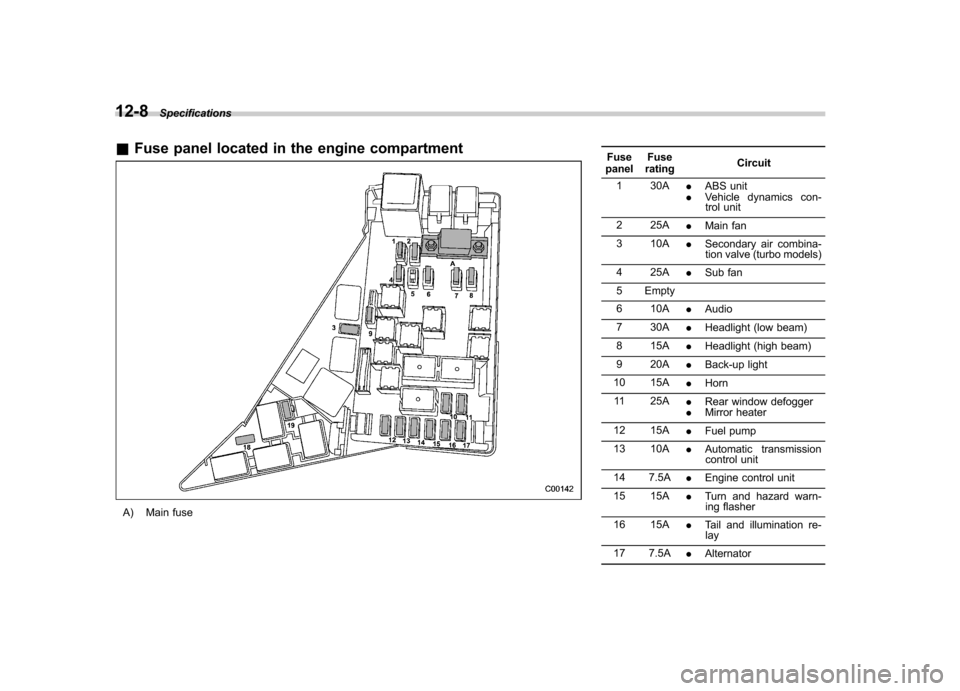
12-8Specifications
&Fuse panel located in the engine compartment
A) Main fuse Fuse
panel Fuse
rating Circuit
1 30A .ABS unit
. Vehicle dynamics con-
trol unit
2 25A .Main fan
3 10A .Secondary air combina-
tion valve (turbo models)
4 25A .Sub fan
5 Empty
6 10A .Audio
7 30A .Headlight (low beam)
8 15A .Headlight (high beam)
9 20A .Back-up light
10 15A .Horn
11 25A .Rear window defogger
. Mirror heater
12 15A .Fuel pump
13 10A .Automatic transmission
control unit
14 7.5A .Engine control unit
15 15A .Turn and hazard warn-
ing flasher
16 15A .Tail and illumination re-
lay
17 7.5A .Alternator