2009 SUBARU FORESTER maintenance schedule
[x] Cancel search: maintenance schedulePage 308 of 384
&Engine coolant
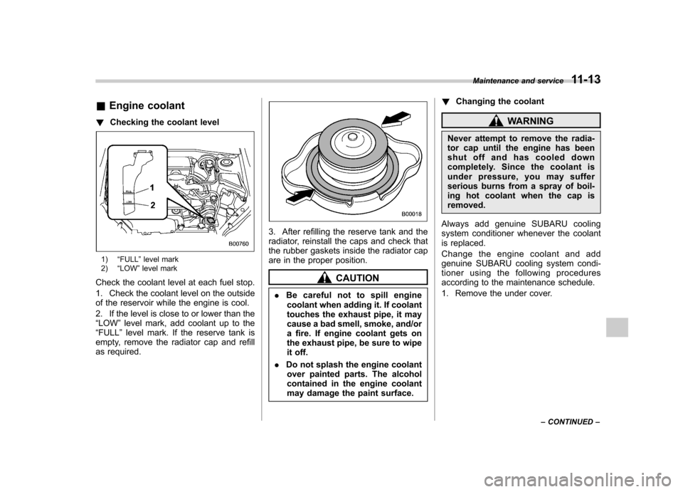
! Checking the coolant level
1) “FULL ”level mark
2) “LOW ”level mark
Check the coolant level at each fuel stop.
1. Check the coolant level on the outside
of the reservoir while the engine is cool.
2. If the level is close to or lower than the “ LOW ”level mark, add coolant up to the
“ FULL ”level mark. If the reserve tank is
empty, remove the radiator cap and refill
as required.
3. After refilling the reserve tank and the
radiator, reinstall the caps and check that
the rubber gaskets inside the radiator cap
are in the proper position.
CAUTION
. Be careful not to spill engine
coolant when adding it. If coolant
touches the exhaust pipe, it may
cause a bad smell, smoke, and/or
a fire. If engine coolant gets on
the exhaust pipe, be sure to wipe
it off.
. Do not splash the engine coolant
over painted parts. The alcohol
contained in the engine coolant
may damage the paint surface. !
Changing the coolant
WARNING
Never attempt to remove the radia-
tor cap until the engine has been
shut off and has cooled down
completely. Since the coolant is
under pressure, you may suffer
serious burns from a spray of boil-
ing hot coolant when the cap isremoved.
Always add genuine SUBARU cooling
system conditioner whenever the coolant
is replaced.
Change the engine coolant and add
genuine SUBARU cooling system condi-
tioner using the following procedures
according to the maintenance schedule.
1. Remove the under cover. Maintenance and service
11-13
– CONTINUED –
Page 311 of 384
11-16Maintenance and service
& Replacing the air cleaner element
Replace the air cleaner element according
to the maintenance schedule in the“ Warranty and Maintenance Booklet ”. Un-
der extremely dusty conditions, replace it
more frequently. It is recommended that
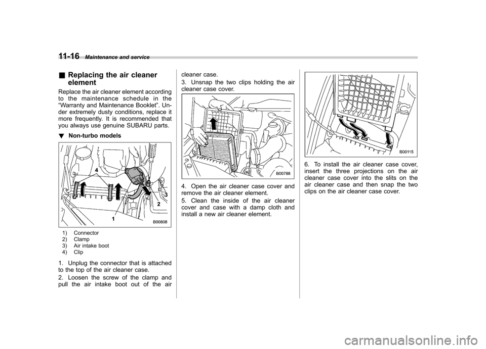
you always use genuine SUBARU parts. ! Non-turbo models
1) Connector
2) Clamp
3) Air intake boot
4) Clip
1. Unplug the connector that is attached
to the top of the air cleaner case.
2. Loosen the screw of the clamp and
pull the air intake boot out of the air cleaner case.
3. Unsnap the two clips holding the air
cleaner case cover.
4. Open the air cleaner case cover and
remove the air cleaner element.
5. Clean the inside of the air cleaner
cover and case with a damp cloth and
install a new air cleaner element.
6. To install the air cleaner case cover,
insert the three projections on the air
cleaner case cover into the slits on the
air cleaner case and then snap the two
clips on the air cleaner case cover.
Page 313 of 384
11-18Maintenance and service
Spark plugs
It may be difficult to replace the spark
plugs. It is recommended that you have
the spark plugs replaced by your
SUBARU dealer.
The spark plugs should be replaced
according to the maintenance schedule
in the“Warranty and Maintenance Book-
let ”.
CAUTION
. When disconnecting the spark
plug cables, always grasp the
spark plug cap, not the cables.
. Make sure the cables are re-
placed in the correct order. &
Recommended spark plugs
Non-turbo models: FR5AP-11 (NGK)
Turbo models:
SILFR6A (NGK) Drive belts
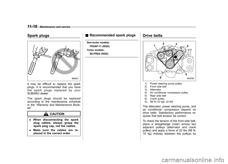
1) Power steering pump pulley
2) Front side belt
3) Alternator
4) Air conditioner compressor pulley
5) Rear side belt
6) Crank pulley
A) 98 N (10 kgf, 22 lbf)
The alternator, power steering pump, and
air conditioner compressor depend on
drive belts. Satisfactory performance re-
quires that belt tension be correct.
To check the tension of the front side belt,
place a straightedge (ruler) across two
adjacent pulleys (alternator and crank
pulley) and apply a force of 22 lbs (98 N,
10 kg) midway between the pulleys by
Page 323 of 384
11-28Maintenance and service
Brake pedal
Check the brake pedal free play and
reserve distance according to the main-
tenance schedule in the “Warranty and
Maintenance Booklet ”.
& Checking the brake pedal
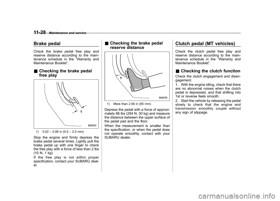
free play
1) 0.02 –0.08 in (0.5 –2.0 mm)
Stop the engine and firmly depress the
brake pedal several times. Lightly pull the
brake pedal up with one finger to check
the free play with a force of less than 2 lbs
(10 N, 1 kg).
If the free play is not within proper
specification, contact your SUBARU deal-
er. &
Checking the brake pedal
reserve distance
1) More than 2.56 in (65 mm)
Depress the pedal with a force of approxi-
mately 66 lbs (294 N, 30 kg) and measure
the distance between the upper surface of
the pedal pad and the floor.
When the measurement is smaller than
the specification, or when the pedal does
not operate smoothly, contact with your
SUBARU dealer. Clutch pedal (MT vehicles)
Check the clutch pedal free play and
reserve distance according to the main-
tenance schedule in the
“Warranty and
Maintenance Booklet ”.
& Checking the clutch function
Check the clutch engagement and disen-gagement.
1. With the engine idling, check that there
are no abnormal noises when the clutch
pedal is depressed, and that shifting into
1st or reverse feels smooth.
2. Start the vehicle by releasing the pedal
slowly to check that the engine and
transmission smoothly couple without
any sign of slippage.
Page 325 of 384
11-30Maintenance and service
result in the need for costly brake
rotor repair or replacement.
& Breaking-in of new brake
pads and linings
When replacing the brake pad or lining,
use only genuine SUBARU parts. After
replacement, the new parts must be
broken in as follows: ! Brake pad and lining
While maintaining a speed of 30 to 40
mph (50 to 65 km/h), step on the brake
pedal lightly. Repeat this five or moretimes. ! Parking brake lining
1.Drivethevehicleataspeedof
approximately 22 mph (35 km/h).
2. With the parking brake release button
pushed in, pull the parking brake lever
SLOWLY and GENTLY. (Pulling with a
force of approximately 33 lbs [147 N, 15kg].)
3. Drive the vehicle for approximately
220 yards (200 meters) in this condition.
4. Wait 5 to 10 minutes for the parking
brake to cool down. Repeat this proce-dure.
5. Check the parking brake stroke. If the
parking brake stroke is out of the specified range, adjust it by turning the adjusting nut
located on the parking brake lever.
Parking brake stroke: 7–8 notches / 44 lbs (196 N, 20 kg)
WARNING
A safe location and situation should
be selected for break-in driving.
CAUTION
Pulling the parking brake lever too
forcefully may cause the rear
wheels to lock. To avoid this, be
certain to pull the lever up slowly
and gently. Parking brake stroke
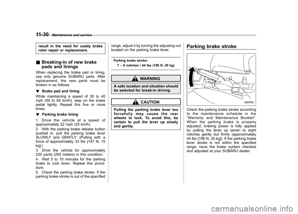
Check the parking brake stroke according
to the maintenance schedule in the“
Warranty and Maintenance Booklet ”.
When the parking brake is properly
adjusted, braking power is fully applied
by pulling the lever up seven to eight
notches gently but firmly (approximately
44 lbs [196 N, 20 kg]). If the parking brake
lever stroke is not within the specified
range, have the brake system checked
and adjusted at your SUBARU dealer.
Page 377 of 384
14-6Index
K Key Number .................................................................. 2-2
Reminder chime. ...................................................... 3-5
Replacement ........................................................... 2-4
Keyless entry system ................................................... 2-7
Keys .......................................................................... 2-2
L
Leather seat materials ................................................ 10-5
License plate light ..................................................... 11-51
Light Cargo area .............................................................. 6-3
Control switch ........................................................ 3-24
Dome ..................................................................... 6-2
Front fog ............................................................... 3-27
Ignition switch .......................................................... 3-5
License plate ........................................................ 11-51
Map ....................................................................... 6-3
Rear combination .................................................. 11-50
Loading your vehicle .................................................. 8-11
Low fuel warning light ........................................... 3-8, 3-17
Low tire pressure warning light .................................... 3-14
Lower and tether anchorage ........................................ 1-29
M
Main fuse ................................................................. 11-45
Maintenance Precautions ........................................................... 11-3
Schedule .............................................................. 11-3
Seatbelt ................................................................ 1-19 Tools
..................................................................... 9-17
Malfunction indicator lamp (check engine warning light)... 3-12 Manual
Climate control system ............................................. 4-3
Seat ....................................................................... 1-3
Transmission ......................................................... 7-13
Transmission oil ................................................... 11-19
Map light .................................................................... 6-3
Maximum load limits ................................................... 8-16
Meters and gauges ...................................................... 3-5
Mirrors ...................................................................... 3-33
Moonroof ................................................................... 2-22
N
New vehicle break-in driving ......................................... 8-2
O
Odometer/Trip meter .................................................... 3-6
Oil filter ..................................................................... 11-9
Oil level Engine .................................................................. 11-8
Front differential gear ............................................ 11-21
Manual transmission ............................................. 11-19
Rear differential .................................................... 11-22
Oil pressure warning light ............................................ 3-13
On-pavement and off-road driving .................................. 8-6
Outside mirrors .......................................................... 3-35
Outside temperature indicator ...................................... 3-22
Overhead console ....................................................... 6-6
Overheating engine .................................................... 9-11