2009 SKODA YETI tyre pressure
[x] Cancel search: tyre pressurePage 202 of 271

Fuel
201
Using the system
Safety
Driving Tips
General Maintenance
Breakdown assistance
Technical Data
It is therefore the case that EN 590 prescribes diesel fuel class for certain periods of the year which can also be purchased at the co
rresponding time during the year. “Winter-
grade diesel fuel” will still operate properly even at a temperature of -20°C. It is often the case in countries with different climatic conditions that diesel fuels avail- able have a different temperature characte
ristic. The authorised Škoda Service Part-
ners and filling stations in the country concer
ned will be able to provide you with infor-
mation regarding the diesel fuels available. Prewarming fuel The vehicle is fitted with a fuel filter prewarming system. This secures operation of a vehicle using diesel fuel down to an environmental temperature of -25°C.
Caution
It is not permitted to add the various fuel
additives on the market, including petrol, to
diesel fuel in order to im
prove its flow properties.
RefuellingFig. 168 Right rear side of the vehicle: Fuel fi
ller flap / fuel filler
flap with cap unscrewed
The filler flap is automatically unlocke
d or locked* with the central locking.
Opening the fuel filler cap– Press in the middle of the left area of
the fuel filler flap in direction of arrow
⇒ fig. 168
.
– The fuel filler cap on the fuel filler tube
must be unlocked to the left using the
vehicle key (only valid for vehicles which
do not have automatic unlocking of the
fuel filler flap).
– Unscrew the fuel filler ca
p anti-clockwise and place the fuel filler cap from above
on the fuel filler flap
⇒fig. 168
on the right.
Closing fuel filler cap– Screw on the cap by turning it to the right until it is heard to lock. – The fuel filler cap on the fuel filler tube
must be locked to the right using the vehicle
key (only valid for vehicles which do not
have automatic locking of the fuel filler
flap).
– Close the fuel filler flap until it locks. The correct grade of fuel for your vehicle as well as the tyre size and inflation pressures are stated on a sticker affixed to the inside of the fuel filler flap. Further information on fuel
⇒page 200.
The fuel tank has a capacity of about 60 litres.
WARNING
Pay attention to any legal requirements if
you do carry a spare canister in the
vehicle. We do not recommend carrying any fuel canisters in your vehicle for safety reasons. The canister can be damaged
in the event of an accident and fuel
may leak out.
Caution
•
Before refuelling it is necessary to switch off the auxiliary heating system (auxiliary
heating and ventilation) *.•
Remove any fuel which has spilled onto th
e paintwork of your vehicle immediately
- risk of paint damage!•
On vehicles fitted with a ca
talytic converter, never let the fuel tank run completely
empty. An irregular supply of fuel to the engine can result in misfiring and unburnt fuel may get into the exhaust system, which may result in overheating and damage to the catalytic converter.
A1
sgg.6.book Page 201 Thursday, September 24, 2009 2:32 PM
Page 216 of 271

Wheels and Tyres
215
Using the system
Safety
Driving Tips
General Maintenance
Breakdown assistance
Technical Data
Wheels and TyresWheelsGeneral information•
New tyres do not offer optimal grip at first and should therefore be run in for about
500 km at a moderate speed and an appropri
ately cautious style of driving. You will
also profit from longer tyre life.•
The tread depth of new tyres may differ because of design features and the config-
uration of the tread (depending on the type of tyre and the manufacturer).•
Drive over curbs on the side of the road
and other such obstacles slowly and,
where possible, at a right angle in order to avoid damage to tyres and wheel trims.•
Inspect your tyres from time to time
for damage (punctures, cuts, splits and
bulges). Remove foreign bodies from the tyre profile.•
Damage to tyres and wheels is frequently
not visible. Unusual vi
brations or pulling
of the vehicle to one side coul
d be a sign of tyre damage.
Please reduce your speed
immediately and stop if you su
spect that a wheel is damaged.
Inspect the tyres for
signs of damage (bulges, splits, etc.). If no
visible damage is present, please drive at an
appropriately slow speed and carefully to the nearest specialist garage in order to have your vehicle inspected.•
Also protect your tyres from contact with oil, grease and fuel.
•
Immediately replace any dust caps of
the valves which have got lost.
•
Mark wheels before removing them so that
their previous dire
ction of running can
be maintained when mounted them again.•
Always store wheels or tyres which been removed in a cool, dry and, where
possible, dark place. Tyres which are not fixed to a wheel trim should be stored upright.
WARNING
•
New tyres during the first 500 km do not offer optimal grip and should
therefore be run appropriately - risk of accident!•
Never drive with damaged tyres - risk of accident!
Note
Please observe the various differing legal requirements regarding tyres.Ty re l i feThe life of your tyres very much depends on the following points: Tyre pressure The working life of tyres will be shortened considerably if the tyres are insufficiently or over-inflated and this will have an adverse
effect on the handling of your vehicle.
Correctly inflated tyres are of particular importance when travelling at
high speeds
. It
is therefore good to check the pressure at
least once a month and also before setting
off on a long trip. Please do not forget the spare wheel when checking the tyres. The tyre inflation pressures for
summer tyres
are indicated on the inside of the fuel
filler flap
⇒fig. 178
. The inflation pressures for
winter tyres
are 20 kPa (0.2 bar) higher
than those for summer tyres
⇒page 218.
The tyre pressure should be at the highest pressure specified for your vehicle at all times. Always check the inflation pressure of tyres when cold. Do not reduce the higher pres- sure of warm tyres. Adapt the inflation pressure of the tyres accordingly if your vehicle is carrying a significantly higher payload.
Fig. 178 An opened fuel filler flap with a tyre size and tyre inflation pressure table
sgg.6.book Page 215 Thursday, September 24, 2009 2:32 PM
Page 217 of 271

Wheels and Tyres
216
Driving style Fast cornering, sharp acceleration and brak
ing (squealing tyres) increase wear-and-
tear on your tyres. Balancing wheels The wheels of a new vehicle are balanced. There are a wide range of influences when driving which may result in an imbalance
and which makes themselves felt through
vibration in the steering. You should have the wheels rebalanced si
nce any imbalance increases wear-and-tear
on the steering, the suspension and tyres. A wheel must also be rebalanced when a new tyre is fitted and each time a tyre is repaired. Wheel alignment errors Incorrect wheel alignment at the front and re
ar will not only increase wear-and-tear on
the tyres but will also has an adverse effect on vehicle safety. Contact your specialist garage if you notice any unusual tyre wear.
WARNING
•
If the inflation pressure is too low,
the tyre must perform a greater flexing
work. At higher speeds the tyre will warm up as a result of this. This can result in tread separation and even a tyre blowout.•
Immediately replace the damaged rims or tyres.
•
Tyres which are 6 years old or more should only be fitted in exceptional
cases and when adopting an approp
riately cautious style of driving.
For the sake of the environment
Tyres which are insufficiently inflated increase your fuel consumption.
Wear indicatorsThe base of the tread of the original tyres has wear indicators 1.6 mm high, installed at right angles to the direction of travel. These
wear indicators are lo
cated at 6 - 8 points
depending on the make and are evenly spaced around the circumference of the tyre ⇒ fig. 179
. Markings on the walls of the tyres
through the letters “TWI”, triangular
symbols or other symbols identify th
e position of the wear indicators.
A re m a i n i n g t re a d o f j u s t 1 .6 m m , m e a s u re d i n t h e g ro o v e s o f t he tre a d n e x t t o th e w e a r indicators, means that your tyres have
reached their legally permissible minimum
tread depth.
WARNING
•
You must have your tyres replaced with new ones at the latest when the
wear indicators have been worn down
. The legally permissible minimum tread
depth should be observed.•
Worn tyres do not provide the necessary adhesion to the road surface at
high speeds on wet roads. One could experience “aquaplaning” (uncontrolled movements of the vehicle - “swimming” on a wet road surface).
Fig. 179 Tyre tread with wear indicators
sgg.6.book Page 216 Thursday, September 24, 2009 2:32 PM
Page 225 of 271
Breakdown assistance
224
The vehicle tool kit and the lifting jack*, on which a sign is affixed, are stowed in a box in the luggage compartment
⇒page 223, fig. 182
; there is also space here for the
detachable ball head of the towing devi
ce*. The box is secured with a strap.
The vehicle tool kit contains the following
parts (depending on equipment fitted):
•
Wire clamps for removing the full wheel trims,
•
Wheel wrench*,
•
To w i n g e y e ,
•
Adapter for the wheel bolts lock*,
•
Replacement bulb set*
15),
•
To r x s c r e w d r i v e r.
Before placing the lifting jack back in its storage area, screw in the arm of the lifting jack fully.
WARNING
•
The factory-supplied lifting jack is only intended for your model of vehicle.
On no account attempt to lift a heavier vehicle or other loads - risk of injury!•
Ensure that the vehicle tool kit is safely attached in the luggage compart-
ment.
Note
Ensure that the box is always secured with the strap.Tyre repair kitThe tyre repair kit is intended for the repair
of minor tyre defects. The tyre repair kit
contains a compressor, inflation bottle,
operating instructions and accessories.
The repair with the tyre repair kit is
not at all intended to replace
a permanent repair
on the tyre, this repair only serves to reach the next specialist garage. The repair can be undertaken on the vehicle immediately.
Please read the attached instructions care-
fully before the repair.
The tyre repair kit is located in
a box in the luggage compartment
⇒page 223,
fig. 182
.
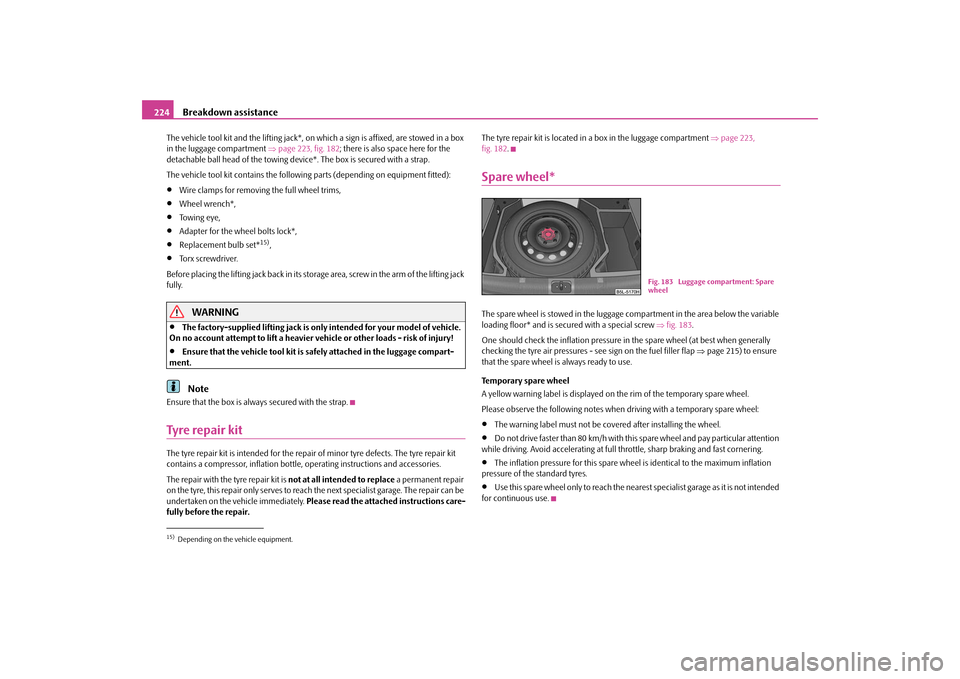
Spare wheel*The spare wheel is stowed in the luggage compartment in the area below the variable loading floor* and is secured with a special screw
⇒fig. 183
.
One should check the inflation pressure in
the spare wheel (at best when generally
checking the tyre air pressures - see sign on the fuel filler flap
⇒page 215) to ensure
that the spare wheel is always ready to use. Temporary spare wheel A yellow warning label is displayed on the rim of the temporary spare wheel. Please observe the following notes when driving with a temporary spare wheel:•
The warning label must not be covered after installing the wheel.
•
Do not drive faster than 80 km/h with this spare wheel and pay particular attention
while driving. Avoid accelerating at full throttle, sharp braking and fast cornering.•
The inflation pressure for this spare wheel is identical to the maximum inflation
pressure of the standard tyres.•
Use this spare wheel only to reach the nearest specialist garage as it is not intended
for continuous use.
15)Depending on the vehicle equipment.
Fig. 183 Luggage compartment: Spare wheel
sgg.6.book Page 224 Thursday, September 24, 2009 2:32 PM
Page 226 of 271

Breakdown assistance
225
Using the system
Safety
Driving Tips
General Maintenance
Breakdown assistance
Technical Data
Changing a wheelPreliminary workThe following steps should be carried ou
t before actually changing the wheel.
– If it is necessary to change a wheel, park
the vehicle as far aw
ay as possible from
the traffic flow. The place you choose should be
level
.
–Have
all the occupants get out.
While changing a wheel, the occupants of the
vehicle should not stand on the ro
ad (e.g. behind a crash barrier).
– Apply the
handbrake
firmly.
–Engage
1st gear
or if your vehicle is fitted with
an automatic gearbox, position the
selector lever into position P
.
– If a trailer is coupled, uncouple it. –Take the
vehicle tool kit
⇒page 223 and the
spare wheel*
⇒page 224 out of the
luggage compartment.
WARNING
•
If you find yourself in flowing traffic switch on the hazard warning lights
system and place the warning triangle on
the side of the road at the prescribed
distance from your vehicle while observing all national legal provisions. In this way you are protecting not only yourself but also other road users.•
Never start the engine with the vehicle si
tting on the raised
jack - danger of
suffering injury.
Caution
If you have to change a wheel on a slope first block the opposite wheel with a stone or similar object in order to secure the
vehicle from unexpectedly rolling away.
Note
Comply with the national legal regulations.
Changing a wheelAlways change a wheel on a level surface as far as possible. – Take off the full wheel trim*
⇒page 226 or the caps
⇒page 226.
– In the case of light alloy wheels remove the wheel trim cap
⇒page 227.
– First of all slacken the safety wheel bolt * and afterwards the other wheel bolts
⇒ page 227.
– Jack up the vehicle until the wheel to
be changed is clear of the ground
⇒ page 227.
– Unscrew the wheel bolts and place them
on a clean surface (cloth, paper etc.).
– Take off the wheel. – Fit on the spare wheel and tighten the wheel bolts slightly.– Lower the car. – Tighten the wheel bolts firmly, alternatel
y and diagonally using the wheel wrench
(crosswise) and last the safety wheel bolt*
⇒page 227.
Note
•
All bolts must be clean and must turn easily.
•
You must never grease or oil the wheel bolts!
•
When fitting on unidirectiona
l tyres, ensure that the tyres rotate in the correct
direction
⇒page 215.
Subsequent stepsAfter changing the wheel, you mu
st perform the following steps.
– Stow the vehicle tool kit in the space provided.– Stow the replaced wheel in the luggage compartment. –
Check
the
tyre pressure
on the spare wheel just mounted as soon as possible.
sgg.6.book Page 225 Thursday, September 24, 2009 2:32 PM
Page 227 of 271

Breakdown assistance
226
– Have the
tightening torque
of the wheel bolts
checked
with a torque wrench as
soon as possible. Steel and light alloy wh
eels must be tightened to a tightening
torque of
120 Nm
.
– Change the damaged wheel or consult a specialist garage about possibilities for
getting repairs done.
WARNING
It is necessary to observe the guidelines given on
⇒page 217 if the vehicle is
subsequently fitted with tyres which are different to those it was fitted with at the works.
Note
•
If you find, when changing the wheel, that
the wheel bolts are corroded and diffi-
cult to turn, the bolts must be replaced
before checking the tightening torque.
•
Drive cautiously and only at a moderate speed to a workshop where the tightening
torque can be checked.Full wheel trim*Pulling off– Hook the clamp found in the vehicle tool
kit into the reinforced edge of the full
wheel trim.
– Push the wheel key through the clamp, support the wheel key at the tyre and pull
off the wheel trim.
Installing– First press the full wheel trim onto the wheel at the valve opening provided. Then
press the full wheel trim into the wheel in
such a way that its entire circumference
locks correctly in place.
Caution
•
Use the pressure of your hand, do not knock on the full wheel trim! Heavy knocks
mainly on the points where the full wheel trim has not been inserted into the wheel, can result in damage to the guide and centering elements of the full wheel trim.•
Check for yourself that the safety wheel bolt
is located in the hole in the area of the
valve before fitting the full wheel trim onto a
steel wheel which is attached with a safety
wheel bolt
⇒page 228.
Wheel bolts with caps*Pulling off– Push the plastic clip sufficie
ntly far onto the cap until th
e inner catches of the clip
are positioned at the collar
of the cap and detach the cap.
Installing– Push the caps fully onto the wheel bolts. The caps are located in the well of the luggage compartment.
Fig. 184 Removing the cap
sgg.6.book Page 226 Thursday, September 24, 2009 2:32 PM
Page 238 of 271

Fuses and light bulbs
237
Using the system
Safety
Driving Tips
General Maintenance
Breakdown assistance
Technical Data
Fuse assignment in the dash panelCertain electrical components are only standard on certain vehicle model versions or only suppliable as optional
equipment for certain models.
No.
Power consumer
Amperes
1
Heating of the gearbox ve
ntilation (diesel engine)
Control unit for automatic gearbox DQ200
1010
2
To w i n g d e v i c e
20
3
To w i n g d e v i c e
15
4
Not assigned
5
Air blower for heating, radiat
or fan, air conditioning sys-
tem, Climatronic
40
6
Rear window wiper
15
7
Not assigned
8
To w i n g d e v i c e
15
9
Central control unit - interior lights
10
10
Rain sensor, light switch, diagnostic socket
10
11
Left side cornering lights
10
12
Right side cornering lights
10
13
Radio, changer for mobile navigation
15
Fig. 196 Schematic representation of the fuse carrier in the dash panel
14
To w i n g d e v i c e
5
15
Light switch
5
16
Heatable washing nozzles, regulator for seat heating
5
17
Control unit for headlamp be
am adjustment and head-
light swivel
5
18
Diagnostic socket, engine
control unit, brake sensor
10
19
Control unit for ABS, ESP, swit
ch for tyre air pressure con-
trol, control unit for parking aid, switch for Offroad mode
5
20
Switch and control unit for airbag
5
21
WIV, parking light, dimming mirrors, pressure sensor, tele- phone preinstallation, air mass meter
5
22
Instrument cluster, control
unit for electromechanical
power steering, Haldex
5
23
Central locking system and bonnet lid
15
24
Rear power window
30
25
Rear wind
ow heater
Rear window he
ater, Auxiliary heating (auxiliary heating
and ventilation)
25 30
26
Power socket in the luggage compartment
20
27
Electric sliding/tilting roof, electric sun screen
30
28
Fuel pump relay, control unit for fuel pump, injection valves
15
29
Front power window
30
30
front and rear lighter
20
31
Headlight cleaning system
20
32
Front seat heating
20
33
Heating, Climatic, Climatronic
7,5
No.
Power consumer
Amperes
sgg.6.book Page 237 Thursday, September 24, 2009 2:32 PM
Page 245 of 271

Technical Data
244
Gearbox code, paint number, interior eq
uipment number, engine output, engine
code Partial description of the vehicle 7GG, 7MB, 7MG - vehicles with DPF
⇒page 170
Vehicle identification number (VIN) The vehicle identification number - VIN (veh
icle body number) is stamped into the
engine compartment on the right hand sh
ock absorber dome. This number is also
located on a sign on the lower left hand edge below the windscreen. Engine number The engine number is stam
ped into the engine block.
Type plate (production plate) The type plate is located in the lowe
r area of the left centre column.
Homologation sign The homologation sign is located on the insi
de of the bonnet next to the lock. Vehicles
for certain countries do not
have an homologation sign.
Sticker on inside of fuel filler flap The stickers are affixed to the inside of the fuel filler flap and contain the following information:•
The prescribed types of fuel,
•
Ty re s i z e ,
•
Tyre pressure.
Fuel consumption according to the regulations (99/100/EU)Depending on the range of the special equipment, style of driving, traffic situation, weather influences and vehicl
e condition, the consumption
values which in practice
result when using the vehicle can deviate from the indicated values.
Urban traffic The consumption measurement in urban traffic
begins with starting of the cold engine.
Afterwards the normal urban traffic is simulated. Non-urban traffic For the consumption measurement in non-ur
ban traffic the vehicle, as in daily
motoring, is accelerated and braked severa
l times in all gears. The vehicle speed
changes within the range from 0 to 120 km/h. Combined traffic The consumption value in the combined traffic consists of 37% from the value for the urban traffic and of 63% from th
e value for the non-urban traffic.
A3A4A5sgg.6.book Page 244 Thursday, September 24, 2009 2:32 PM