2009 Seat Ibiza ST heater
[x] Cancel search: heaterPage 180 of 250

Checking and refilling levels179
Safety First
Operating instructions
Practical tips
Technical Data
Winter driving
Diesel can thicken in winter.Winter-grade diesel
When using “summer-grade diesel fuel”, difficulties may be experienced at
sub-zero temperatures because the fuel thickens due to wax separation.
Therefore, “winter-grade diesel fuel” is available in some countries during
the cold months. It can be used at temperatures as low as -22°C.
In countries with different climatic conditions the diesel fuel generally sold
has different temperature characteristics. Check with an Authorised Service
Centre or filling stations in the country concerned regarding the type of diesel
fuels available.
Filter pre-heater
Your vehicle is fitted with a fuel filter glow plug system, making it well
equipped for operation in winter. This ensures that the fuel system remains
operational to approx. -24°C, provided you use winter-grade diesel which is
safe to -15°C.
However, if the fuel has waxed to such an extent that the engine will not start
at temperatures of under -24° C, simply place the vehicle in a warm place for
a while.
Caution
Do not mix fuel additives (“thinners”, or similar additives) with diesel fuel.
Working in the engine compartmentSafety instructions on working in the engine compartment
Any work carried out in the engine compartment or on the
engine must be carried out cautiously.Before starting any work on the engine or in the engine compart-
ment:
1. Switch off the engine and remove the key from the ignition.
2. Apply the handbrake.
3. Move the gear lever to neutral or the gear lever to position P.
4. Wait for the engine to cool down.
5. Keep children away from the vehicle.
6. Raise the bonnet ⇒page 181.You should not do any work in the engine compartment unless you know
exactly how to carry out the jobs and have the correct tools! Have the work
carried out by a qualified workshop if you are uncertain.
All service fluids and consumables, e.g. coolant, engine oil, spark plugs and
batteries, are being constantly developed. SEAT provides a constant flow of
information to the Authorised Service Centres concerning modifications. For
this reason, we recommend you to have service fluids and consumables
replaced by an Authorised Service Centre. Please observe the relevant
instructions ⇒page 172. The engine compartment of the vehicle is a
hazardous area ⇒.
Ibiza ST_EN.book Seite 179 Dienstag, 12. Januar 2010 4:03 16
Page 187 of 250

Checking and refilling levels
186•Never pour oil down drains or into the ground.•Use a suitable container when draining the used oil. It must be large
enough to hold all the engine oil.CoolantCoolant specifications
Coolant is a mixture of water and at least 40% coolant addi-
tive.The cooling system must be filled with a mixture of water and at least 40 % of
our coolant additive G 12++ or an additive with the specification TT-VW 774 G
(known for its purple colour). This mixture provides the necessary frost
protection down to -25°C and protects the alloy parts of the cooling system
against corrosion. It also prevents scaling and raises the boiling point of the
coolant.
The concentration of coolant must always be at least 40% - even if frost
protection is not required.
If greater frost protection is required in very cold climates, the proportion of
the antifreeze additive G 12++ can be increased. However, the percentage of
coolant additives should not exceed 60%, as this would reduce the frost
protection. It would also reduce the cooling effect. A mixture with 60% anti-
freeze additive will give frost protection to approx. -40°C.
WARNING
•The coolant additive is toxic. There is a toxic risk. Always keep the
coolant additive in the original container which should be stored out of the
reach of children. The same applies to coolant which you have drained off.
•The coolant additive G 12++ must be added in sufficient quantities to
provide anti-freeze protection at the coldest ambient temperatures that
can be expected. At extremely cold outside temperatures, the coolant could
freeze, causing the vehicle to breakdown. As the heater would also not
work in this situation, there is a risk of suffering exposure!Caution
•Other additives may give considerably inferior corrosion protection. The
resulting corrosion in the cooling system can lead to a loss of coolant,
causing serious damage to the engine.•If add it ive G 12 ++ is not availa ble , t his can b e m ixed wi th G 12 +, b ea ri ng in
mind that the protection against corrosion will be reduced.WARNING (continued)
Ibiza ST_EN.book Seite 186 Dienstag, 12. Januar 2010 4:03 16
Page 211 of 250

If and when
210The individual electrical circuits are protected by fuses. The fuses are located
behind a cover at the left-hand end of the dash panel. When the steering
wheel is on the right, the fuses are on the right-hand side of the dash panel,
behind a cover.
The electric windows are protected by circuit breakers . These reset automat-
ically after a few seconds when the overload (caused for example by frozen
windows) has been corrected.
Fuses colour code
WARNING
Never “repair” damaged fuses and never replace them with fuses with a
higher rating. Failure to comply could result in fire. This could also cause
damage to other parts of the electrical system.
Note
•If a newly replaced fuse blows again after a short time, the electrical
system must be checked by a qualified workshop as soon as possible.•If you replace a fuse with higher-rating fuse, you could cause damage to
another location in the electrical system.
•Always keep some spare fuses in the vehicle. These are available from
SEAT dealers.Fuses on left side of dash panelFuses
Colour
Amps
Beige
5
Brown
7,5
Red
10
Blue
15
Ye ll ow
20
Natural (white)
25
Green
30
Number
Consumer
Amps
1
Power steering/Engine operation
7,5
2
Diagnostics/Heater/Autoclimate/Cli-
matronic/Electric anti-dazzle mirror/Naviga-
tor/Air conditioning pressure switch/ Climate
fan/ Kisi/ AFS Control unit/Coming home
relay/Soundaktor
10
3
Petrol engine control unit/Flow meter/Diesel
engine control unit/Relay coils/Engine opera-
tion/Bi-turbo fuel control unit
5
4
ABS/ESP switch (turning sensor)/Light lever
10
5
Reverse light/Heating nozzles
10
6
Instrument panel
5
7
Rear fog light
5
8
Vaca n t
9
Headlight lever
10
10
Headlight lever/Clutch (Petrol)/Brakes (all)
5
11
Airbag control unit
5
12
Automatic gearbox/ Headlight lever
10
13
Exterior mirror control
5
Ibiza ST_EN.book Seite 210 Dienstag, 12. Januar 2010 4:03 16
Page 213 of 250

If and when
212Fuses below steering wheel in relay holderPTC fuses
AUX 1 Fuses
AUX 3 Fuses
Fuses in engine compartment above batteryNon-metal fuses
Some of the electrical items listed in the table are only fitted on certain
models or are optional extras.
Please note that the above list contains all data at the time of going to press,
so it is subject to modifications.
56
Rear windscreen wiper
10
57
Dipped beam headlight (right side)
15
58
Dipped beam headlight (left side)
15
Number
Consumer
Amps
1
Supplementary electrical heating using air
40
2
Supplementary electrical heating using air
40
3
Supplementary electrical heating using air
40
Number
Consumer
Amps
1
Dipped headlight (left side)
15
2
Dipped headlight (right side)
15
3
Headlight washer pump
20
Number
Consumer
Amps
1
Trailer control unit
15
2
Trailer control unit
20
3
Trailer control unit
20
Number
Consumer
Amps
Number
Consumer
Amps
1
ABS unit
25
2
Electroblower clima heater/fan
30
3
Climate fan
5
4
ABS unit
10
5
Electronic control unit
5
6
Injection module
30
Fig. 138 Fuses in engine
compartment
Ibiza ST_EN.book Seite 212 Dienstag, 12. Januar 2010 4:03 16
Page 224 of 250

If and when223
Safety First
Operating instructions
Practical tips
Technical Data
Jump leads
Jump leads must comply with the standard
DIN 72553 (see manufacturer's
documentation). The wire cross section must be at least 25 mm
2 for petrol
engines and at least 35 mm
2 for diesel engines.
Note
•The vehicles must not touch each other, otherwise electricity could flow as
soon as the positive terminals are connected.•The discharged battery must be properly connected to the vehicle elec-
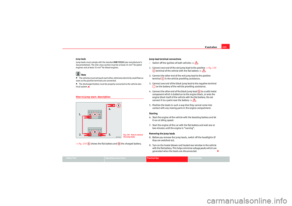
trical system.How to jump start: description⇒ fig. 159 shows the flat battery and the charged battery. Jump lead terminal connections
– Switch off the ignition of both vehicles
⇒.
1. Connect one end of the red jump lead to the positive ⇒fig. 159
terminal of the vehicle with the flat battery ⇒.
2. Connect the other end of the red jump lead to the positive terminal in the vehicle providing assistance.
3. Connect one end of the black jump lead to the negative terminal on the battery of the vehicle providing assistance.
4. Connect the other end of the black jump lead to a solid metal component which is bolted on to the engine block, or onto the
engine block itself of the vehicle with the flat battery. Do not
connect it to a point near the battery ⇒.
5. Position the leads in such a way that they cannot come into contact with any moving parts in the engine compartment.
Starting
6. Start the engine of the vehicle with the boosting battery and let it run at idling speed.
7. Start the engine of the car with the flat battery and wait one or two minutes until the engine is “running”.
Removing the jump leads
8. Before you remove the jump leads, switch off the headlights (if they are switched on).
9. Turn on the heater blower and heated rear window in the vehicle with the flat battery. This helps minimise voltage peaks which are
generated when the leads are disconnected.
Fig. 159 How to connect
the jump leads
AA
AB
A+
A+
A-
AX
Ibiza ST_EN.book Seite 223 Dienstag, 12. Januar 2010 4:03 16