Page 214 of 257
If and when
212Double headlamps
Main beam
Side lights
Dipped headlights
Side lights
Indicator light
Turn signal lamps– Raise the bonnet.
– Rotate the bulb holder ⇒fig. 134 to the left and pull.
– Remove the bulb by pressing on the lamp holder and rotating at the same time to the left.
– Installation is in the reverse order.
Fig. 133 Double head-
lamps
AAABACADAE
Fig. 134 Indicator light
AA
Ibiza_EN.book Seite 212 Montag, 14. September 2009 6:19 18
Page 215 of 257
If and when213
Safety First
Controls and equipment
Practical tips
Technical Data
Dipped and side lights– Raise the bonnet. – Remove the loop
⇒fig. 135 in the direction of the arrow and
remove the cover.
– Remove the connector ⇒fig. 136 from the bulb.
– Unclip the retainer spring ⇒fig. 136 , pressing inwards to the
right.
– Extract the bulb and fit the replacement so that the rim of the attachment plate is on the reflector cut-out.
Fig. 135 Dipped head-
lightsFig. 136 Side lights
A1
A2A3
Ibiza_EN.book Seite 213 Montag, 14. September 2009 6:19 18
Page 216 of 257
If and when
214Main beam and side lights– Raise the bonnet. – Move the loop in the direction of the arrow and remove the
cover ⇒fig. 137 .
– Remove the connector by pulling outward.
– Extract the bulb and fit the replacement so that it sits correctly in the cut-out on the reflector.
– Installation is in the reverse order.
Single headlamps
Side lights - Dipped beam/main beam.
Indicator
Fig. 137 Main beam
headlightsFig. 138 Side lights
A2
Fig. 139 Single head-
lamp
AAAB
Ibiza_EN.book Seite 214 Montag, 14. September 2009 6:19 18
Page 218 of 257
If and when
216
– Remove the loop ⇒page 215, fig. 141 in the direction of the
arrow and remove the cover.
– Remove the connector ⇒page 215, fig. 142 from the bulb.
– Unclip the retainer spring ⇒page 215, fig. 142 , pressing
inwards to the right.
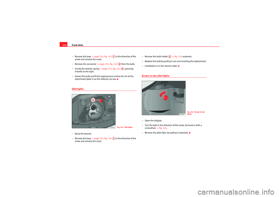
– Extract the bulb and fit the replacement so that the rim of the attachment plate is on the reflector cut-out.Side lights – Raise the bonnet.
– Remove the loop ⇒page 215, fig. 141 in the direction of the
arrow and remove the cover. – Remove the bulb holder
⇒fig. 143 outwards.
– Replace the bulb by pulling it out and inserting the replacement.
– Installation is in the reverse order.
Access to rear pilot lights–Open the tailgate.
– Turn the bolt in the direction of the arrow, by hand or with a screwdriver ⇒fig. 144 .
– Remove the pilot light, by pulling it outwards.
A1
A2A3
Fig. 143 Side lights
A1
A4
Fig. 144 Access to rear
lights
Ibiza_EN.book Seite 216 Montag, 14. September 2009 6:19 18
Page 219 of 257
If and when217
Safety First
Controls and equipment
Practical tips
Technical Data
Changing bulbs on rear lights– Remove the connector from housing ⇒page 216, fig. 144 .– Remove the lamp holder, separating it from the casing. To do
this, press tabs in the direction of the arrows ⇒fig. 145 .
– When the lamp holder has been removed, press in the direction of the arrow and at the same time, turn in the direction of the
arrow ⇒fig. 146 .
Side indicator lamps– Press the indicator to the left or to the right to remove the lamp.
– Remove the lamp holder from the indicator.
– Remove the failed bulb and replace with a new bulb.
– Insert the lamp holder in the indicator guide until it clicks into
place.
Fig. 145 Changing bulbs
on rear lightsFig. 146 Changing bulbs
on rear lights
AA
AB
A1
A2
Fig. 147 Side indicators
Ibiza_EN.book Seite 217 Montag, 14. September 2009 6:19 18
Page 221 of 257
If and when219
Safety First
Controls and equipment
Practical tips
Technical Data
– First fit the glass with the fastening tabs over the frame of the
switch. Next press the front part until the two long tabs click on
the support.Additional brake lights*Given the difficulty involved in the replacement of this light it should be done
by the Technical Service.Boot light*
– Extract the tulip shaped fitting by pressing on the inside edge of this -arrow- using the flat side of a screwdriver ⇒fig. 149 .
– Press the lamp sideways and remove from its housing ⇒fig. 150 .Jump-startingJump leads
The jump lead must have a su fficient wire cross section.If the engine fails to start because of a discharged battery, the battery can be
connected to the battery of another vehicle to start the engine.
Fig. 149 Luggage
compartment light
Fig. 150 Luggage
compartment light
Ibiza_EN.book Seite 219 Montag, 14. September 2009 6:19 18
Page 222 of 257
If and when
220Jump leads
Jump leads must comply with the standard DIN 72553 (see manufacturer's
documentation). The wire cross section must be at least 25 mm
2 for petrol
engines and at least 35 mm
2 for diesel engines.
Note
•The vehicles must not touch each other, otherwise electricity could flow as
soon as the positive terminals are connected.•The discharged battery must be properly connected to the vehicle elec-
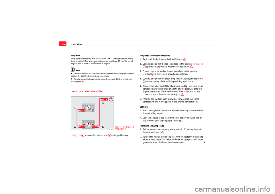
trical system.How to jump start: description⇒ fig. 151 shows a flat battery and a charged battery. Jump lead terminal connections
– Switch off the ignition on both vehicles ⇒
.
1. Connect one end of the red jump lead to the positive ⇒fig. 151
terminal of the vehicle with the flat battery ⇒.
2. Connect the other end of the red jump lead to the positive terminal in the vehicle providing assistance.
3. Connect one end of the black jump lead to the negative terminal on the battery of the vehicle providing assistance.
4. Connect the other end of the black jump lead to a solid metal component which is bolted on to the engine block, or onto the
engine block itself of the vehicle with the flat battery. Do not
connect it to a point near the battery ⇒.
5. Position the leads in such a way that they cannot come into contact with any moving parts in the engine compartment.
Starting
6. Start the engine of the vehicle with the boosting battery and let it run at idling speed.
7. Start the engine of the car with the flat battery and wait one or two minutes until the engine is “running”.
Removing the jump leads
8. Before you remove the jump lead s, switch off the headlights (if
they are switched on).
9. Turn on the heater blower and rear window heater in the vehicle with the flat battery. This helps minimise voltage peaks which are
generated when the leads are disconnected.
Fig. 151 How to connect
the jump leads
AA
AB
A+
A+
A-
AX
Ibiza_EN.book Seite 220 Montag, 14. September 2009 6:19 18
Page 225 of 257

If and when223
Safety First
Controls and equipment
Practical tips
Technical Data
Do not pull too hard with the towing vehicle and take care to avoid jerking the
tow-rope. When towing on an unpaved road, there is always a risk of over-
loading and damaging the anchorage points.
The ignition of the vehicle being towed must be switched on to prevent the
steering wheel from locking and also to allow the use of the turn signals,
horn, windscreen wipers and washers.
As the brake servo does not work if the engine is not running, you must apply
considerably more pressure to the brake pedal than you normally would.
As the power assisted steering does not work if the engine is not running, you
will need more strength to steer than you normally would.
Towing vehicles with an automatic gearbox
•Put the selector lever into position “N”.•Do not drive faster than 50 km/h when towing a vehicle.•Do not tow further than 50 km.•If a breakdown vehicle is used, the vehicle must be towed with the front
wheels raised.Note
•Observe legal requirements when towing or tow-starting.•Switch on the hazard warning lights of both vehicles. However, observe
any regulations to the contrary.•For technical reasons, vehicles with an automatic gearbox must not be
tow-started.•If damage to your vehicle means that there is no lubricant in the gearbox,
you must raise the drive wheels while the vehicle is being towed.•If the vehicle has to be towed more than 50 km, the front wheels must be
raised during towing, and towing should be carried out by a qualified person.•The steering wheel is locked when the vehicle has no electrical power. The
vehicle must then be towed with the front wheels raised. Towing should be
carried out by a qualified person.
•The towing eye should always be kept in the vehicle.Trailer eyesFitting the towing eye
– Take the towing ring from the onboard tool set.
– Remove the front cover by pressing down on its left-hand side. For FR finishes, press down and pull outwards.
– Screw the eye in to its limit to the left, in the direction of the arrow
⇒ fig. 152 .
Fig. 152 Fitting the
towing eye to the front of
the vehicle
Ibiza_EN.book Seite 223 Montag, 14. September 2009 6:19 18