Page 17 of 209
40A-12
GENERAL INFORMATION
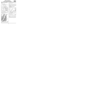
Earths on body: List and location of components
40A
For the earth stud fitting procedure, see MR 400.
WARNING
To avoid damaging the vehicles electric and electro-
nic components, the earths of any wiring harness
near the weld area must be disconnected.
Position the earth of the welding machine as closely
as possible to the weld area (see MR 400).
121241
Page 18 of 209
40A-13
GENERAL INFORMATION
Earths on body: List and location of components
40A
DETAILED VIEW OF THE POSITION OF EARTHS
ON THE VEHICLE
Earth stud on the front right-hand wing lower bracket
(1) .
Earth stud on the bulkhead (2) .Earth stud on the front left-hand side member and scu-
ttle side panel (3) .
Earth stud on the front left-hand wing lower bracket (4)
.
121247
121246
121245
121248
Page 19 of 209
40A-14
GENERAL INFORMATION
Earths on body: List and location of components
40A
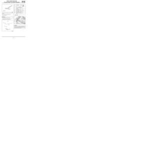
Earth stud on the tunnel (5) .
Earth stud on the right-hand rear quarter lining (6) .Earth stud on the rear quarter lining (7) .
125408
121249121250
Page 20 of 209

40A-15
GENERAL INFORMATION
Vehicle structure, front section: Description
40A
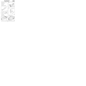
FRONT STRUCTURE
125409
No. Description Classification Type Thickness
(mm)
(1) Scuttle side panel upper reinforcement (see 42A, Front upper structure, Upper reinforcement
of scuttle side panel: Description, page 42A-19)
(2) Scuttle side panel (see 42A, Front upper structure, Scuttle side panel:
Description, page 42A-16)
(3) Front section of front side member clo-
sure panel (see 41A, Front lower structure, Front side member clo-
sure panel, front section: Description, page 41A-13)
(4) Centre floor front side cross member (see 41B, Centre lower structure, Centre floor front
side cross member: Description, page 41B-7)
(5) Front side member rear part (see 41A, Front lower structure, Front side member,
rear section: Description, page 41A-15)
(6) Front side member front section (see 41A, Front lower structure, Front side member,
front section: Description, page 41A-8)
(7) front-end lower cross member (see 41A, Front lower structure, Front end lower cross
member: Description, page 41A-2)
(8) Front mounting of front sub-frame (see 41A, Front lower structure, Front subframe front
mounting: Description, page 41A-18)
Page 21 of 209
40A-16
GENERAL INFORMATION
Vehicle structure, front section: Description
40A
(9) Engine stand (see 41A, Front lower structure, Engine stand: Descrip-
tion, page 41A-21)
(10) Front left-hand wheel arch (see 42A, Front upper structure, Front wheel arch: Des-
cription, page 42A-22)
(11) Front half unit (see 41A, Front lower structure, Front half unit: Des-
cription, page 41A-24)
(12) Front right-hand wheel arch (see 42A, Front upper structure, Front wheel arch: Des-
cription, page 42A-22)
(13) Front wheel arch, front section (see 42A, Front upper structure, Front wheel arch: Des-
cription, page 42A-22) No. Description Classification Type Thickness
(mm)
Page 22 of 209
40A-17
GENERAL INFORMATION
Vehicle structure, side section: Description
40A
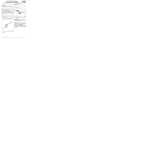
SIDE STRUCTURE
120919
No. Description Classification Type Thickness
(mm)
(1) Roof drip moulding lining (see MR 400)HLE1.3
(2) Normal roof front cross member (see 45A, Top of body, Roof
front cross member: General
description, page 45A-8) Mild
steel1
(3) Roof rear cross member (see 45A, Top of body, Roof
rear cross member: General
description, page 45A-10) HLE1.2
(4) Sill pane stiffener (see 41C, Side lower structure, Sill panel stiffener: Des-
cription, page 41C-15)
(5) Sill panel reinforcement (see 41C, Side lower structure, Sill panel reinforce-
ment: Description, page 41C-13)
(6) A-pillar reinforcement (see 43A, Side upper structure, A-pillar reinforcement:
Description, page 43A-6)
(7) Sill panel closure panel (see 41C, Side lower structure, Sill panel closure panel:
Description, page 41C-10)
Page 23 of 209
40A-18
GENERAL INFORMATION
Vehicle structure, side section: Description
40A
(8) B-pillar reinforcement (see 43A, Side upper structure, B-pillar reinforcement:
Description, page 43A-10)
(9) Windscreen pillar lining (see Windscreen pillar lining: Description)
(10) A-pillar (see 43A, Side upper structure, A-pillar: Description,
page 43A-2)
(11) Roof centre cross member (see Roof centre cross member: Description)
(12) Front section of roof (see 45A, To p of body, Roof front section: Description,
page 45A-6)
(13) Sill panel (see 41C, Side lower structure, Sill panel: Description,
page 41C-5)
(14) Roof (see 45A, Top of body, Roof: Description, page 45A-2)
(15) Upper body (see 43A, Side upper structure, Upper body: Descrip-
tion, page 43A-17)
(16) Rear section of roof (see 45A, Top of body, Roof rear section: Description,
page 45A-7) No. Description Classification Type Thickness
(mm)
Page 24 of 209

40A-19
GENERAL INFORMATION
Vehicle structure, centre section: Description
40A
CENTRAL STRUCTURE
120918
No. Description Classification Type Thickness
(mm)
(1) Central floor reinforcement (see 41A, Front lower struc-
ture, Front side member, rear
section: Description, page 41A-
15) HLE1.5
(2) Front side member offset stiffener (see 41B, Centre lower struc-
ture, Centre floor, side section:
Description, page 41B-3) Ve r y
high
yield
strength2.5
(3) Windscreen aperture lower cross
member closure panel (see 42A, Front upper structure, Windscreen aperture
lower cross member closure panel: Description, page
42A-28)
(4) Centre floor, side section (see 41B, Centre lower structure, Centre floor, side
section: Description, page 41B-3)
(5) Front cross member under front seat (see 41B, Centre lower structure, Front cross member
under front seat: Description, page 41B-9)
(6) Rear cross member under front seat (see 41B, Centre lower structure, Rear cross member
under front seat: Description, page 41B-11)