2009 RENAULT TWINGO RS spark plugs
[x] Cancel search: spark plugsPage 70 of 348

17B-70V7 MR-413-X44-17B000$131.mif
PETROL INJECTION
Fault finding – Interpretation of faults17B
SIM 32 Injection
Program no.: D3
Vdiag No.: 44, 4C, 50
and 54
DF059
CONTINUED 1
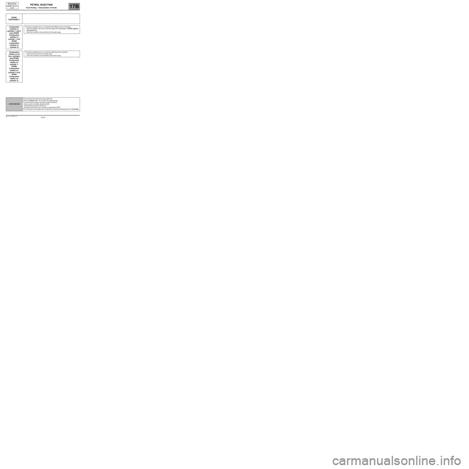
Combustion
misfire on
cylinders 1 and 4
(see DF059
Combustion
misfire on
cylinder 1 and
DF062
Combustion
misfire on
cylinder 4)
The fault is probably due to a component that affects the torque of cylinders 1 and 4:
–check the ignition coil circuit concerned (apply the interpretation of DF361 Ignition
coil circuit 1-4),
–check the condition and conformity of the spark plugs.
Combustion
misfire on all
four cylinders
(see DF060
Combustion
misfire on
cylinder 2,
DF061
Combustion
misfire on
cylinder 3, and
DF062
Combustion
misfire on
cylinder 4).The fault is probably due to a component affecting all the cylinders:
–check that the correct fuel is being used,
–check the condition and conformity of the spark plugs.
AFTER REPAIREnsure that all the faults have been dealt with.
Clear the stored faults. Do not clear the programming.
To check that the system has been properly repaired:
- there must be no further electrical faults,
- programming has been carried out,
- the engine should be warm (minimum temperature 75˚C)
Run the engine at idle speed with all electrical consumers drawing power for 15 minutes.
Page 73 of 348

17B-73V7 MR-413-X44-17B000$131.mif
PETROL INJECTION
Fault finding – Interpretation of faults17B
SIM 32 Injection
Program no.: D3
Vdiag No.: 44, 4C, 50
and 54
DF060
CONTINUED 1
Combustion
misfire on
cylinders 2 and 3
(see DF060
Combustion
misfire on
cylinder 2 and
DF061
Combustion
misfire on
cylinder 3)
The fault is probably due to a component that affects the torque of cylinders 2 and 3:
–check the relevant ignition coil circuit (apply the interpretation of fault DF362
Ignition coil circuit 2-3),
–check the condition and conformity of the spark plugs.
Misfiring on all
four cylinders
(see DF059
Misfiring on
cylinder 1,
DF061 Misfiring
on cylinder 3,
and DF062
Misfiring on
cylinder 4).The fault is probably due to a component affecting all the cylinders:
–check that the correct fuel is being used,
–check the condition and conformity of the spark plugs.
AFTER REPAIREnsure that all the faults have been dealt with.
Clear the stored faults. Do not clear the programming.
To check that the system has been properly repaired:
- there must be no further electrical faults,
- programming has been carried out,
- the engine should be warm (minimum temperature 75˚C)
Run the engine at idle speed with all electrical consumers drawing power for 15 minutes.
Page 76 of 348

17B-76V7 MR-413-X44-17B000$131.mif
PETROL INJECTION
Fault finding – Interpretation of faults17B
SIM 32 Injection
Program no.: D3
Vdiag No.: 44, 4C, 50
and 54
DF061
CONTINUED 1
Misfires in
cylinders 2 and 3
(see DF060
Misfires in
cylinder 2 and
DF061 Misfires
in cylinder 3)
The fault is probably due to a component that affects the torque of cylinders 2 and 3:
–check the relevant ignition coil circuit (apply the interpretation of fault DF362
Ignition coil circuit 2-3),
–check the condition and conformity of the spark plugs.
Combustion
misfire on all
four cylinders
(see DF059
Combustion
misfire on
cylinder 1,
DF060
Combustion
misfire on
cylinder 2 and
DF062
Combustion
misfire on
cylinder 4).The fault is probably due to a component affecting all the cylinders:
–check that the correct fuel is being used,
–check the condition and conformity of the spark plugs.
AFTER REPAIREnsure that all the faults have been dealt with.
Clear the stored faults. Do not clear the programming.
To check that the system has been properly repaired:
- there must be no further electrical faults,
- programming has been carried out,
- the engine should be warm (minimum temperature 75˚C)
Run the engine at idle speed with all electrical consumers drawing power for 15 minutes.
Page 79 of 348

17B-79V7 MR-413-X44-17B000$131.mif
PETROL INJECTION
Fault finding – Interpretation of faults17B
SIM 32 Injection
Program no.: D3
Vdiag No.: 44, 4C, 50
and 54
DF062
CONTINUED 1
Combustion
misfires in
cylinders 1 and 4
(see DF059
Combustion
misfires in
cylinder 1 and
DF062
Combustion
misfires in
cylinder 4)
The fault is probably due to a component that affects a pair of cylinders:
–check the ignition coil circuit concerned (apply the interpretation of DF361 Ignition
coil circuit 1-4),
–check the condition and conformity of the spark plugs.
Combustion
misfire on all
four cylinders
(see DF059
Combustion
misfire on
cylinder 1,
DF060
Combustion
misfire on
cylinder 2 and
DF061
Combustion
misfire on
cylinder 3).The fault is probably due to a component affecting all the cylinders:
–check that the correct fuel is being used,
–check the condition and conformity of the spark plugs.
AFTER REPAIREnsure that all the faults have been dealt with.
Clear the stored faults. Do not clear the programming.
To check that the system has been properly repaired:
- there must be no further electrical faults,
- programming has been carried out,
- the engine should be warm (minimum temperature 75˚C)
Run the engine at idle speed with all electrical consumers drawing power for 15 minutes.
Page 135 of 348

17B-135V7 MR-413-X44-17B000$133.mif
PETROL INJECTION
Fault finding – Interpretation of faults17B
SIM 32 Injection
Program no.: D3
Vdiag No.: 44, 4C, 50
and 54
DF330
CONTINUEDPINKING SENSOR CIRCUIT1.DEF: Abnormal voltage
2.DEF: EOBD
Use the universal bornier to check the insulation and continuity of the following connections:
●3S between components 120 and 146,
●3DQ between components 120 and 146.
If the connection or connections are faulty and there is a repair procedure (see Technical Note 6015A, Electrical
wiring repair, Wiring: Precautions for repair), repair the wiring, otherwise replace it.
Check the conformity of the fuel in the tank, apply test 1 Petrol conformity check.
Check that the spark plugs are correct.
Repair if necessary.
AFTER REPAIRFollow the instructions to confirm repair:
–If the fault is present, continue to deal with the fault.
–If the fault is stored, ignore it.
Deal with any other faults.
Clear the stored faults.
Page 147 of 348

17B-147V7 MR-413-X44-17B000$133.mif
PETROL INJECTION
Fault finding – Interpretation of faults17B
SIM 32 Injection
Program no.: D3
Vdiag No.: 44, 4C, 50
and 54
DF436
CONTINUED
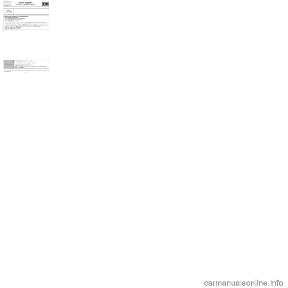
If the fault is still present, carry out the following checks:
–check the flywheel signal sensor,
–check the condition and cleanliness of the flywheel,
–check the flywheel signal sensor mounting,
–check the flywheel/sensor air gap
–check the cylinder compressions,
–check the entire petrol supply system (see MR 411 (NEW TWINGO), MR 442 (E33), MR 392 (CLIO III), or
MR 385 (MODUS), Mechanical, Engine and peripherals,13A, Fuel supply),
–check the entire ignition system (see MR 411 (NEW TWINGO), MR 442 (E33), MR 392 (CLIO III), or MR 385
(MODUS), Mechanical, Engine and peripherals, 17A, Ignition, Coil and spark plugs),
–check that the correct fuel is being used,
–check that the spark plugs are correct.
If the fault is still present, contact the Techline.
AFTER REPAIREnsure that all the faults have been dealt with.
Clear the stored faults. Do not clear the programming.
To check that the system has been properly repaired:
–there must be no further electrical faults,
–programming has been carried out,
the engine must be warm (minimum 75˚C), and idling, with all electrical consumers
running for 15 minutes.
Page 196 of 348

17B-196V7 MR-413-X44-17B000$151.mif
PETROL INJECTION
Fault finding – Interpretation of statuses17B
SIM 32 Injection
Program no.: D3
Vdiag No.: 44, 4C, 50
and 54
ET054
CONTINUED
IDLING SPEED TOO LOW
Check:
–engine oil level (too high, splashing),
–that the exhaust pipe is not blocked (catalytic converter damaged),
–the cleanliness and conformity of the air filter,
–that the air inlet circuit is not blocked,
–that the throttle valve assembly is not clogged,
–the condition and conformity of the spark plugs,
–the fuel circuit sealing,
–the fuel pressure and the flow (see MR 392 (Clio III), MR 385 (Modus), MR 411 (New Twingo), or MR 442
(E33), Mechanical, 13A, Fuel supply),
–the condition and cleanliness of the injectors,
–the cylinder compression's,
–the timing setting.
Repair or replace the faulty components, if necessary.
IDLING SPEED TOO HIGH
Check:
–engine oil level (too high, splashing),
–for the fittings in the oil vapour rebreathing system,
–the sealing between the throttle valve and inlet manifold,
–the manifold pressure sensor sealing,
–the fuel vapour absorber bleed, which must not be jammed open,
–the fuel vapour absorber bleed system sealing,
–the brake servo system sealing,
–the sealing between the inlet manifold and cylinder head,
–the oil vapour recovery circuit sealing between the inlet manifold and cylinder head,
–the fuel pressure and the flow (see MR 392 (Clio III), MR 385 (Modus), MR 411 (New Twingo), or MR 442
(E33), Mechanical, 13A, Fuel supply),
–the condition and cleanliness of the injectors,
–the cylinder compression's,
–the timing adjustment,
Repair or replace the faulty components, if necessary.
AFTER REPAIRCarry out a road test, then check with the diagnostic tool.
Page 283 of 348

17B-283V7 MR-413-X44-17B000$171.mif
PETROL INJECTION
Fault finding – Interpretation of parameters17B
SIM 32 Injection
Program no.: D3
Vdiag No.: 44, 4C, 50
and 54
PR095ANTI-PINKING CORRECTION
PARAMETER
DEFINITIONThis parameter indicates the anti-pinking correction in volts.
NOTESThere must be no present or stored faults.
Use the Wiring Diagrams Technical Note for NEW TWINGO, E33, CLIO III or
MODUS.
Conformity check with engine stopped and ignition on, or engine running, and engine coolant
temperature > 80˚C
The pinking sensor must not supply a zero signal, proving that it is recording the mechanical vibrations of the
engine.
Carry out these checks if PR095 is not between 0 V and 8 V.
Check the conformity of the fuel in the tank, apply test 1 Petrol conformity check.
Repair if necessary.
Check the condition and conformity of the spark plugs.
Repair if necessary.
Check the tightness of the pinking sensor (20 Nm).
Repair if necessary.
Check the condition of the pinking sensor connector (component code 146) and the engine management computer
connector (component code 120).
If the connector or connectors are faulty and if there is a repair procedure (see Technical Note 6015A, Repairing
electrical wiring, Wiring: Precautions for repair), repair the connector, otherwise replace the wiring.
Use the universal bornier to check the insulation and continuity of the following connections:
●3S between components 120 and pinking sensor shielding,
●3S between components 120 and 146,
●3DQ between components 120 and 146.
If the connection or connections are faulty and there is a repair procedure (see Technical Note 6015A, Electrical
wiring repair, Wiring: Precautions for repair), repair the wiring, otherwise replace it.
If the fault is still present, replace the pinking sensor.
SIM32_V44_PR095/SIM32_V4C_PR095/SIM32_V50_PR095/SIM32_V54_PR095
AFTER REPAIRCarry out a road test followed by a check with the diagnostic tool.