Page 216 of 348

17B-216V7 MR-413-X44-17B000$152.mif
PETROL INJECTION
Fault finding – Interpretation of statuses17B
SIM 32 Injection
Program no.: D3
Vdiag No.: 44, 4C, 50
and 54
ET143
CONTINUED
Sensor electrical conformity
Check:
–the condition of the low-speed fan unit,
–that the low-speed fan resistance is correct,
–the cleanliness of the low-speed fan earth,
–the low-speed fan feed,
–the feed line between the low-speed fan and the low-speed fan relay.
Check the connection and condition of the connector of the low-speed fan assembly relay (component code 700)
and of the engine management computer (component code 120).
If the connector or connectors are faulty and if there is a repair procedure (see Technical Note 6015A, Electrical
wiring repair, Wiring: Precautions for repair), repair the connector, otherwise change the wiring.
Disconnect the low-speed fan relay. Check, with the ignition on, for 12 V on the connection 3FB of the relay.
If the connection is faulty and if there is a repair procedure (see Technical Note 6015A, Electrical wiring repair,
Wiring: Precautions for repair), repair the wiring, otherwise replace it.
Check the continuity of the relay coil.
Replace the low-speed fan relay if necessary.
Use the universal bornier to check the insulation and continuity of the following connection:
●3JN between components 120 and 700.
If the connection is faulty and if there is a repair procedure (see Technical Note 6015A, Electrical wiring repair,
Wiring: Precautions for repair), repair the wiring, otherwise replace it.
AFTER REPAIRCarry out a road test followed by a check with the diagnostic tool.
Page 218 of 348

17B-218V7 MR-413-X44-17B000$152.mif
PETROL INJECTION
Fault finding – Interpretation of statuses17B
SIM 32 Injection
Program no.: D3
Vdiag No.: 44, 4C, 50
and 54
ET144
CONTINUED
Check:
–the condition of the high-speed fan unit,
–that the high-speed fan resistance is correct,
–the cleanliness of the high-speed fan earth,
–the high-speed fan feed,
–the feed line between the high-speed fan and the high-speed fan relay.
Check the connection and condition of the high-speed fan assembly relay connector (component code 234) and
the engine management computer connector (component code 120).
If the connector or connectors are faulty and if there is a repair procedure (see Technical Note 6015A, Electrical
wiring repair, Wiring: Precautions for repair), repair the connector, otherwise change the wiring.
Disconnect the high-speed fan relay. Check, with the ignition on, for 12 V on the connection 3FB of the relay.
If the connection is faulty and if there is a repair procedure (see Technical Note 6015A, Electrical wiring repair,
Wiring: Precautions for repair), repair the wiring, otherwise replace it.
Check the continuity of the relay coil.
Replace the high-speed fan relay if necessary.
Use the universal bornier to check the insulation and continuity of the following connection:
3JP between components 120 and 234.
If the connection is faulty and if there is a repair procedure (see Technical Note 6015A, Electrical wiring repair,
Wiring: Precautions for repair), repair the wiring, otherwise replace it.
Repair if necessary.
AFTER REPAIRCarry out a road test followed by a check with the diagnostic tool.
Page 241 of 348

17B-241V7 MR-413-X44-17B000$152.mif
PETROL INJECTION
Fault finding – Interpretation of statuses17B
SIM 32 Injection
Program no.: D3
Vdiag No.: 44, 4C, 50
and 54
ET562FAN ASSEMBLY REQUEST BY AUTOMATIC TRANSMISSION (applies only for the sequential gearbox on engine D4F 772)
STATUS
DEFINITIONPRESENT: This status indicates that there has been a fan assembly request from the
transmission.
ABSENT: This status indicates that there has not been a fan assembly request from the
transmission.
NOTESSpecial notes:
Only perform these tests if the parameters do not correspond with the system operation
programming.
There must be no present or stored faults.
Conformity check with engine stopped and ignition on, or engine running, and engine coolant
temperature > 80˚C
PRESENT
or
ABSENTThe status is PRESENT or ABSENT depending on the computer program (engine oil
temperature).
SIM32_V44_ET562/SIM32_V4C_ET562/SIM32_V50_ET562/SIM32_V54_ET562
AFTER REPAIRCarry out a road test followed by a check with the diagnostic tool.
Page 262 of 348
17B-262V7 MR-413-X44-17B000$153.mif
PETROL INJECTION
Fault finding – Interpretation of statuses17B
SIM 32 Injection
Program no.: D3
Vdiag No.: 50 and 54
ET840CUSTOMISED OIL CHANGE INTERVAL
STATUS
DEFINITIONACTIVE: This status indicates that the OCS function is active.
INACTIVE: This status indicates that the OCS function is inactive.
NOTESNone.
Conformity check: Engine stopped and ignition on, or engine running at idle speed, and engine coolant
temperature > 80˚C.
ACTIVE
or
INACTIVE
This status indicates if the vehicle offers the OCS (Oil Control System) function, i.e.
the customised oil change interval.
SIM32_V50_ET840 / SIM32_V54_ET840
AFTER REPAIRCarry out a road test, then check with the diagnostic tool.
Page 264 of 348
17B-264V7 MR-413-X44-17B000$160.mif
PETROL INJECTION
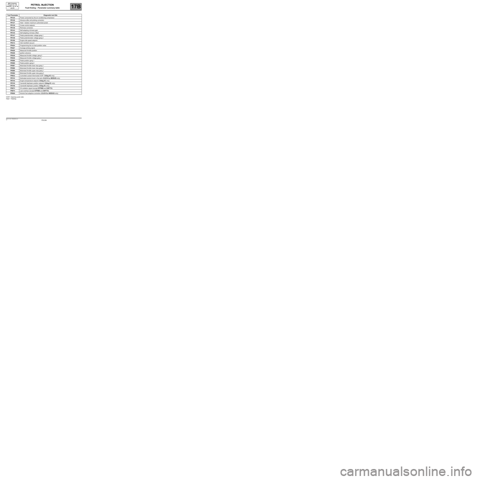
Fault finding – Parameter summary table17B
SIM 32 Injection
Program no.: D3
Vdiag No.: 44, 4C, 50
and 54
OCR*: Opening cyclic ratio
Heat.*: Heating
Tool ParameterDiagnostic tool title
PR125Power consumed by the air conditioning compressor
PR126Advance after anti-pinking correction
PR127Heat.* resistor maximum authorised power
PR130Cruise control setpoint
PR138Richness correction
PR143Self-adapting richness gain
PR144Self-adapting richness offset
PR147Pedal potentiometer voltage gang 1
PR148Pedal potentiometer voltage gang 2
PR190Engine idle speed setpoint.
PR312Inlet manifold vacuum
PR424Programming the no-load position value
PR427Average pinking signal
PR429Measured throttle position
PR448Ignition advance
PR538Measured throttle voltage, gang 2
PR539Measured throttle voltage gang 1
PR568Pedal position gang 1
PR569Pedal position gang 2
PR587Motorised throttle lower stop gang 1
PR588Motorised throttle lower stop gang 2
PR589Motorised throttle upper stop gang 1
PR590Motorised throttle upper stop gang 2
PR632Controlled coolant thermostat OCR* (Vdiag 4C only)
PR743Estimated alcohol level in the tank (CLIO III or MODUS only)
PR744Engine temperature setpoint (Vdiag 4C only)
PR745Camshaft dephaser position setpoint (Vdiag 4C only)
PR746Camshaft dephaser position (Vdiag 4C only)
PR873Oil oxidation signal (except D7F800 and D4F772)
PR874Last overhaul (except D7F800 and D4F772)
PR926Alcohol fuel adaptive correction (CLIO III or MODUS only)
Page 274 of 348

17B-274V7 MR-413-X44-17B000$171.mif
PETROL INJECTION
Fault finding – Interpretation of parameters17B
SIM 32 Injection
Program no.: D3
Vdiag No.: 44, 4C, 50
and 54
PR041
CONTINUED
–Check the cleanliness of the air filter.
–Replace the filter if necessary.
–Check that the air inlet circuit is not blocked.
The turbocharging system must be perfectly sealed, from the exhaust manifold to the turbocharger, from the
turbocharger to the heat exchanger and from the heat exchanger to the throttle valve.
Check that there are no air leaks:
–around the turbocharger pressure sensor,
–around the air temperature sensor.
Check absence of leaks in the wastegate capsule pressure circuit connected to the turbocharger system.
Check that the air-air heat exchanger is not clogged (presence of oil).
If there is oil in the heat exchanger, the turbocharger is certainly damaged.
Using a pressure/vacuum pump, check that the turbocharger protection and turbocharging valve capsule
diaphragms do not leak.
Check the condition the motorised throttle valve in terms of clogging.
AFTER REPAIRCarry out a road test followed by a check with the diagnostic tool.
Page 308 of 348
17B-308V7 MR-413-X44-17B000$172.mif
PETROL INJECTION
Fault finding – Interpretation of parameters17B
SIM 32 injection
Program no.: D3
Vdiag No.: 44, 4C, 50
and 54
PR190IDLE SPEED SETPOINT
PARAMETER
DEFINITIONThis parameter indicates the idle speed setpoint in rpm.
NOTESSpecial notes:
Only perform these tests if the parameters do not correspond with the system operation
programming.
Conformity check: Engine stopped and ignition on, or engine running, and engine coolant temperature
> 80˚C.
The idle speed regulation setting depends on coolant and oil temperature, the position of the gearbox selector, and
what electrical consumers are running.
The value should be:
PR190 ≈ 1000 rpm.
If there is a fault, apply interpretation of ET054 Idle speed regulation.
SIM32_V44_PR190 / SIM32_V4C_PR190 / SIM32_V50_PR190 / SIM32_V54_PR190
AFTER REPAIRCarry out a road test, then check with the diagnostic tool.
Page 324 of 348

17B-324V7 MR-413-X44-17B000$172.mif
PETROL INJECTION
Fault finding – Interpretation of parameters17B
SIM 32 injection
Program no.: D3
Vdiag No.: 44, 4C, 50
and 54
* OCS: Oil Control System.
PR873OIL OXIDATION SIGNAL
(except D7F800 and D4F772)
PARAMETER
DEFINITIONThis parameter indicates the distance of the vehicle when the oil dilution threshold is
reached.
NOTESOnly apply the interpretation of this parameter if the OCS* strategy is activated on the
instrument panel. Check the configuration reading LC106 OCS on the instrument panel
computer is WITH.
Conformity check: Engine stopped and ignition on, or engine running, and engine coolant temperature
> 80˚C.
The oil condition is calculated by the oxidation program in the injection computer, according to the number of
engine revolutions.
When this count reaches a certain threshold before the end of the oil service period, the injection computer
sends a signal to the instrument panel, which will display service due. Parameter PR873 corresponds to
the vehicle mileage at the time this signal is sent.
Then the instrument panel computer deducts 900 miles (1500 km) before displaying the message Service required.
IMPORTANT:
When the message Service due appears on the instrument panel, the customer must have the oil changed within
the remaining 900 miles (1500 km).
SIM32_V44_PR873 / SIM32_V4C_PR873 / SIM32_V50_PR873 / SIM32_V54_PR873
AFTER REPAIRCarry out a road test, then check with the diagnostic tool.
Repeat the conformity check from the start.

