Page 25 of 33

88B-25
AFTER REPAIRRun the multiplex network test again using the diagnostic tool.
Clear the stored faults on all the computers connected to the network.
Deal with any other faults.
V3 MR-413-X44-88B000$070.mif
MULTIPLEXING
Fault finding – Interpretation of faults88B
FAULTY COMPUTER (continued 2)
Multimedia multiplex network
YESFor radio R1-08 and radio R2-08
Check that the resistance is approximately 120 ΩΩ Ω Ω
between the two connections 107X
and 107W on component 261:
–If the resistance is not approximately 120 Ω, contact Techline.
–If the resistance is 120 ΩΩ Ω Ω
, check the continuity and the absence of interference
resistance of multimedia multiplex connection 107X and 107W between
components 225 and component 653.
If the connection or connections are faulty and there is a repair procedure (see
Technical Note 6015A, Electrical wiring repair, Wiring: Precautions for repair),
repair the wiring, otherwise replace it.
Check that the resistance is approximately 120 ΩΩ Ω Ω
between the two connections 107X
and 107W on component 653:
–If the resistance is not approximately 120 Ω, contact Techline.
For the Multimedia connection (C-box)
Check that the resistance is approximately 120 ΩΩ Ω Ω
between the two connections 107X
and 107W on component 1959:
–If the resistance is not approximately 120 Ω, contact Techline.
–If the resistance is 120 ΩΩ Ω Ω
, check the continuity and the absence of interference
resistance of multimedia multiplex connection 107X and 107W between
components 225 and component 653
If the connection or connections are faulty and there is a repair procedure (see
Technical Note 6015A, Electrical wiring repair, Wiring: Precautions for repair),
repair the wiring, otherwise replace it.
Check that the resistance is approximately 120 ΩΩ Ω Ω
between the two connections 107X
and 107W on component 653:
–If the resistance is not approximately 120 Ω, contact Techline.
NO Repair the multimedia multiplex connections 107X and 107W between
components 225 and 653.
Page 26 of 33

88B-26
AFTER REPAIRRun the multiplex network test again using the diagnostic tool.
Clear the stored faults on all the computers connected to the network.
Deal with any other faults.
V3 MR-413-X44-88B000$070.mif
MULTIPLEXING
Fault finding – Interpretation of faults88B
FAULTY COMPUTER (continued 3)
Isolate the faulty segment by disconnecting both ends of the segment. Check the condition of the connectors.
Check the continuity and insulation of the multiplex network H and multiplex network L (connection code
107W and 107X) between the two connectors of the isolated segment.
To obtain the track allocation for the computer and connections, refer to the multimedia multiplex network diagram
for the vehicle.
Perform the necessary operations to check the continuity of the two lines (for example, replacing the wiring).
Make sure that the computer present in the vehicle is compatible and that the data it is producing is correct.
Reconnect the segment.
Run the multiplex network test again using the diagnostic tool.
Is the segment still declared faulty?
NOEnd of fault finding.
YESAre there other faulty segments?
NO
Repeat the multiplex network tests to check the continuity and insulation of the
multimedia multiplex network lines H and L (connection code 107W and 107X)
between the end of the faulty segment and component 225.
YESApply the same procedure to each segment.
Page 27 of 33

88B-27
AFTER REPAIRRun the multiplex network test again using the diagnostic tool.
Clear the stored faults on all the computers connected to the network.
Deal with any other faults.
V3 MR-413-X44-88B000$070.mif
MULTIPLEXING
Fault finding – Interpretation of faults88B
UNRECOGNISED COMPUTERS ON THE NETWORK
NOTES–Check computer compatibility with the vehicle.
E.g.: Certain computers such as Radio R1-08 might not be recognised because a
type A3 display is fitted (in place of a type A2 display).
Check that the CLIP diagnostic tool update is recent enough to be able to deal with faults on the vehicle.
–Switch to computer fault finding mode.
Attempt to establish dialogue with computers.
If there is no communication from the computers to the diagnostic tool: see ALP 1
No dialogue with the computers or computers not communicating with the diagnostic tool.
Check the connections to the computers and that there are no open circuits.
Repair if necessary.
If there is communication with computers:
Make sure that the computer identification information is correct and matches the vehicle in fault finding.
–Check that the following computer information is correct:
–Vdiag:
–Program No.: (injection computer)
If no faults or open or short circuits have been detected after these tests, contact Techline.
Page 28 of 33
88B-28V3 MR-413-X44-88B000$080.mif
88B
ALP 1 No dialogue with computers
NOTESVehicle computer power supply for fault finding:
Engine stopped, ignition on.
Connect the diagnostic tool and perform the required operations.
Try the diagnostic tool on another vehicle.
Check that the tool has been updated with the latest version.
Check:
–the connection between the diagnostic tool and the diagnostic socket (component 225) (connection and cable
in good condition),
–the supplies of the computers,
–the engine and passenger compartment fuses.
MULTIPLEXING
Fault finding – Fault finding chart
Page 29 of 33
 through the following")
88B-29V3 MR-413-X44-88B000$080.mif
MULTIPLEXING
Fault finding – Fault finding chart88B
ALP 1
CONTINUED 1
Check for the supply and earth on the diagnostic socket (component 225) through the following connections: BP19
(+12 V), NAM and MAM (earth). If the checks are correct then move on to the next step, depending on the type of
sensor used:
1.Renault fault finding sensor (with wire connection only):
Check that the CLIP sensor is supplied through the computer's USB port and the diagnostic socket by checking
that the red diodes illuminate. If it is not, try with another cable, another sensor or another clip in order to determine
the defective component.
Check that the CLIP sensor communicates with the vehicle computers by checking that the two green LEDs on the
sensor light up. If it is not, check that the test conditions have been met ( + after ignition feed, vehicle selection
etc.) otherwise apply the electrical checks below.
green diodes red diodes
CAN Vehicle supply through diagnostic socket
ISO Sensor supply through USB port
Page 30 of 33
:
Deal with the fault find")
88B-30V3 MR-413-X44-88B000$080.mif
MULTIPLEXING
Fault finding – Fault finding chart88B
ALP 1
CONTINUED 2
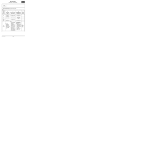
2.Alliance fault finding sensor (with wireless connection possible):
Deal with the fault finding for each warning light in the following order of priority: from warning light 1 to warning
light 3.
Description
of warning
lights
displayed
on the
sensor from
left to rightWarning light 1
shows the supply
statusWarning light 2 shows
the type and status of
the connectionWarning light 3 shows
the level of
communication with
the vehicleReserved
for the
Nissan tool
OffSensor not
connected to the
vehicle or
connection faultNo connection to clip or
connection faultNo dialogue with the
computers-
GreenSensor supplied Wireless connectionGreen flashing:
communication in
progress-
Orange-Connection with USB
port--
RedInitialisation fault - Communication error -
To be
checkedIf red or off:
–Initialisation or
connection fault.
Disconnect and
reconnect several
times. If the result
is not conclusive,
try with another
sensor.If off:
–Wireless connection:
Try connecting with a
USB cable. If the
warning light
illuminates orange,
then check the
configuration of the
wireless connection. If
it is not correct, call
Techline.
–Wire connection: Try
with another USB
cable or another CLIP
sensor or even another
sensor to determine
the faulty component.If warning light 3 is off
or red and warning
light 2 is on:
–in this case, during the
multiplex network test
check that the green
warning light flashes
and that the test
conditions have been
met (+ after ignition
feed, vehicle
selection, etc.)
otherwise apply the
electrical checks
below.If the
warning
light is on:
Contact
Techline.
Page 31 of 33

88B-31V3 MR-413-X44-88B000$080.mif
MULTIPLEXING
Fault finding – Fault finding chart88B
ALP 1
CONTINUED 3
Check the following connections on the diagnostic socket:
BP 19 + Battery
NAM and MAM (or MAN) Earth
If the connection or connections are faulty and there is a repair procedure (see Technical Note 6015A, Electrical
wiring repair, Wiring: Precautions for repair), repair the wiring, otherwise replace the wiring.
Computer connected to multiplex line V
If the fault is still present, check the continuity and the insulation of the following connections:
133B of component 225.
133C of component 225.
Use a multimeter to check that the voltages at the terminals of component 225 are approximately:
–2.5 V between CAN H (133B) and earth (NAM and MAM) (Average values)
–2.5 V between CAN L (133C) and earth (NAM and MAM) (Average values).
Computer connected to Multimedia multiplex line
If the fault is still present, check the continuity and the insulation of the following connections:
107W of component 225.
107X of component 225.
Use a multimeter to check that the voltages at the terminals of component 225 are approximately:
–2.5 V between CAN H (107W) and earth (NAM and MAM) (Average values)
–2.5 V between CAN L (107X) and earth (NAM and MAM) (Average values).
Refer to the Introduction - Repair advice to detect a short circuit on the vehicle's multiplex network.
Page 32 of 33

88B-32V3 MR-413-X44-88B000$080.mif
MULTIPLEXING
Fault finding – Fault finding chart88B
ALP 2No topology diagram or configuration table display at the end of
the multiplex network test
The topology cannot be displayed under the following conditions:
1. The two computers storing the multiplex network configuration have failed to respond.
2. The multiplex network is not operational; therefore dialogue is impossible.
3. The two computers storing the multiplex network configuration do not have the same configurations.
4. On the Multiplex network tab on the configuration screen, an incorrect Diagram version number has been
entered into one of the two computers that store the network configuration.
5. No Network version has been entered into the two computers that store the configuration.
1 –
Vehicle multiplex network
The two computers storing the multiplex network configuration did not respond.
Check first that the computers storing the configuration (Airbag and UCH) are correctly supplied:
–check for earth on connection NAP, and for +12 V supply on connection AP25 on component 756.
–check for earth on connections MAM and NAM, and for +12 V supply on connections AP7, AP43, BP3, BP6,
BP15, BP19, BP49 on component 645.
Check the condition of the multiplex network and the continuity and insulation of the CAN H and CAN L lines
between the computers storing the configuration.
Multimedia multiplex network
The computer containing the multiplex network configuration did not respond.
Check first that the computer storing the configuration (A2/A3 display) is correctly supplied:
check for earth on connection NAM, and for +12 V supply on connection BCP4 and BPT to the display 653.
Check the condition of the multiplex network and the continuity and insulation of the CAN H and CAN L lines
between the computers storing the configuration.
2 – The multiplex network is not operational, therefore dialogue is impossible
(see fault "Multiplex network not operational").
3 – The computers storing the multiplex network configuration do not have the same configurations
(see configuration "Multiplex network configurations").
4 –On the multiplex network tab of the configuration screen, an incorrect diagram version number has
been entered on one of the two computers storing the network configuration
(see configuration "Network configuration").
5 – No diagram version has been entered on the two computers storing the configuration.
(see configuration "Network configuration").